CNC Mill
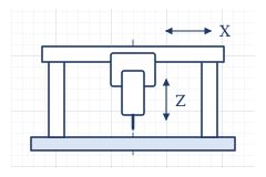
This is a build log for a DIY portable gantry CNC machine designed for drilling holes in large weldments and plates. The bottom is open so it can be set directly onto a workpiece or on a workbench stand. It is currently in the design stage, and the physical machine has not been built yet. The values shown here are from calculations and reference materials, and have not been verified on an actual machine.
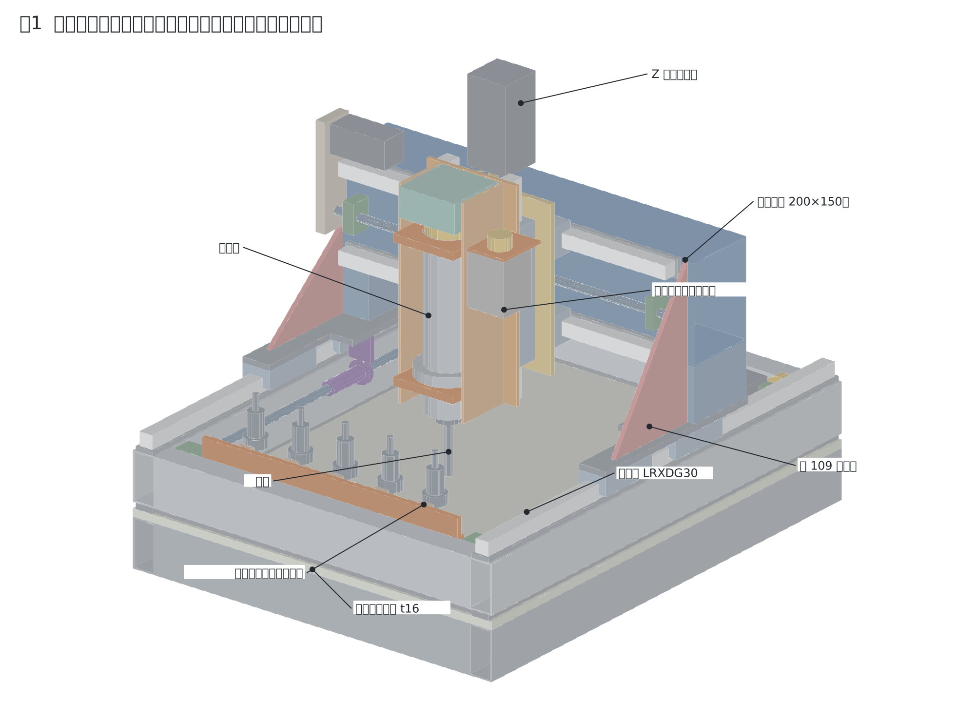
Capabilities (Targets)
| Main machining | Drilling plate (thickness 9–32 mm), slotting blocks, rigid tapping, thread milling, light milling |
| Spindle reach | 656×456 mm (522×456 mm with tool rack installed) |
| Z stroke | 150 mm |
| Spindle | BT30, 1 kW servo with 2:1 belt. Rated 6.4 N·m, max 3000 rpm |
| Drilling | Up to φ12. Larger holes via end mill helical milling |
| Tool changer | BT30 automatic tool changer. 5-tool rack |
| Accuracy target | Diameter 0.01 mm (finish boring), position ±0.05 mm |
| Rapid feed | 3 m/min |
| Dimensions | 1000×800 mm, height approx. 750 mm (approx. 550 mm when retracted) |
| Weight | Machine approx. 189 kg, stand approx. 140 kg |
| Control | LinuxCNC and Mesa 7I76EU (candidate) |
| Estimated cost | Approx. 400,000–500,000 yen (excluding steel stock, machining costs, and tax) |
Documentation
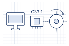
- Control and Electrical ConfigurationFor control, we use LinuxCNC with a Mesa Ethernet card. The …
- Why We Chose This ConfigurationHere is a summary of why we chose this machine type and thes…
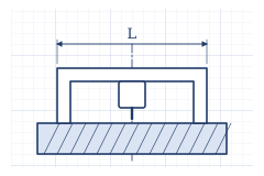
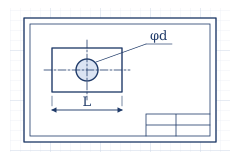
- Design DocumentsDesign documents for the ROBO100 CNC machine. For an overall…
- Shopping ListSurveyed in 2026-11. Prices are as displayed on the sales pa…
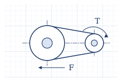
- Component CalculationsCalculations for cutting forces, the spindle, and feed axes.…
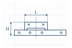
- Parts Documentation買う部品の仕様と寸法や、手持ちの部品の確かめ方をまとめたページです。
| Document | Contents |
|---|---|
| Machine Shape and Dimensions | Overview of the current design |
| Stand and Plate Clamping Methods | Workbench stand, keyway positioning, and clamping |
| Tool Changer Rack | Changing procedure and dimensions |
| Machining Methods for Precision Holes | Choosing between drilling, helical milling, and boring |
| Bill of Materials and Dimensioned Drawings | List of custom-fabricated parts and purchased components |
| Structural Analysis Calculations | Finite element analysis (FEA) for all proposals |
| Component Calculations | Cutting forces, spindle, feed axes, etc. |
| Reasons for Configuration Choices | Why we chose these types and components |
| Control and Electrical Configuration | LinuxCNC, I/O, and power supply |
| Purchased Component Specs and Dimensions | Mounting dimensions and reference sources |
| Measuring Linear Guide Play | Inspection procedure for on-hand guides |
| Shopping List | Candidates and price estimates |
Next Steps
- Measure the play, length, and rigidity of the linear guides on hand to finalize the rail cut positions and frame dimensions.
- Source the head and spindle servo, and verify the fit of dimensions and controls.
- Create fabrication drawings that include mounting holes.
- Build the frame, have the mounting surfaces outsourced for machining, and assemble it.
- Measure accuracy on a test plate and compensate for pitch errors.
QR code for this page
https://robo100.jp/en/000002
No comments yet.