How to Mount the Stand and Plates
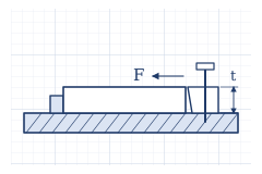
A design idea for the stand that supports the machine when machining small parts and plates. It targets drilling and slotting plates 9 to 32 mm thick. The stand sits on top of a workbench. Heights take the underside of the frame as 0, with units in mm.
Summary
- The top surface is a 1000×800, t16 plate with tapped holes. The frame rests directly on this plate.
- Locating is done with 3 keys.
- Plates are clamped from the side using M8 wedge-type clamps. Because the clamps barely protrude upward, tool clearance can be small.
- The weight is about 140 kg. Together, the machine and stand weigh about 345 kg, so check the load capacity of the workbench (the workbench we use is rated for 1 t).
Stand Plate
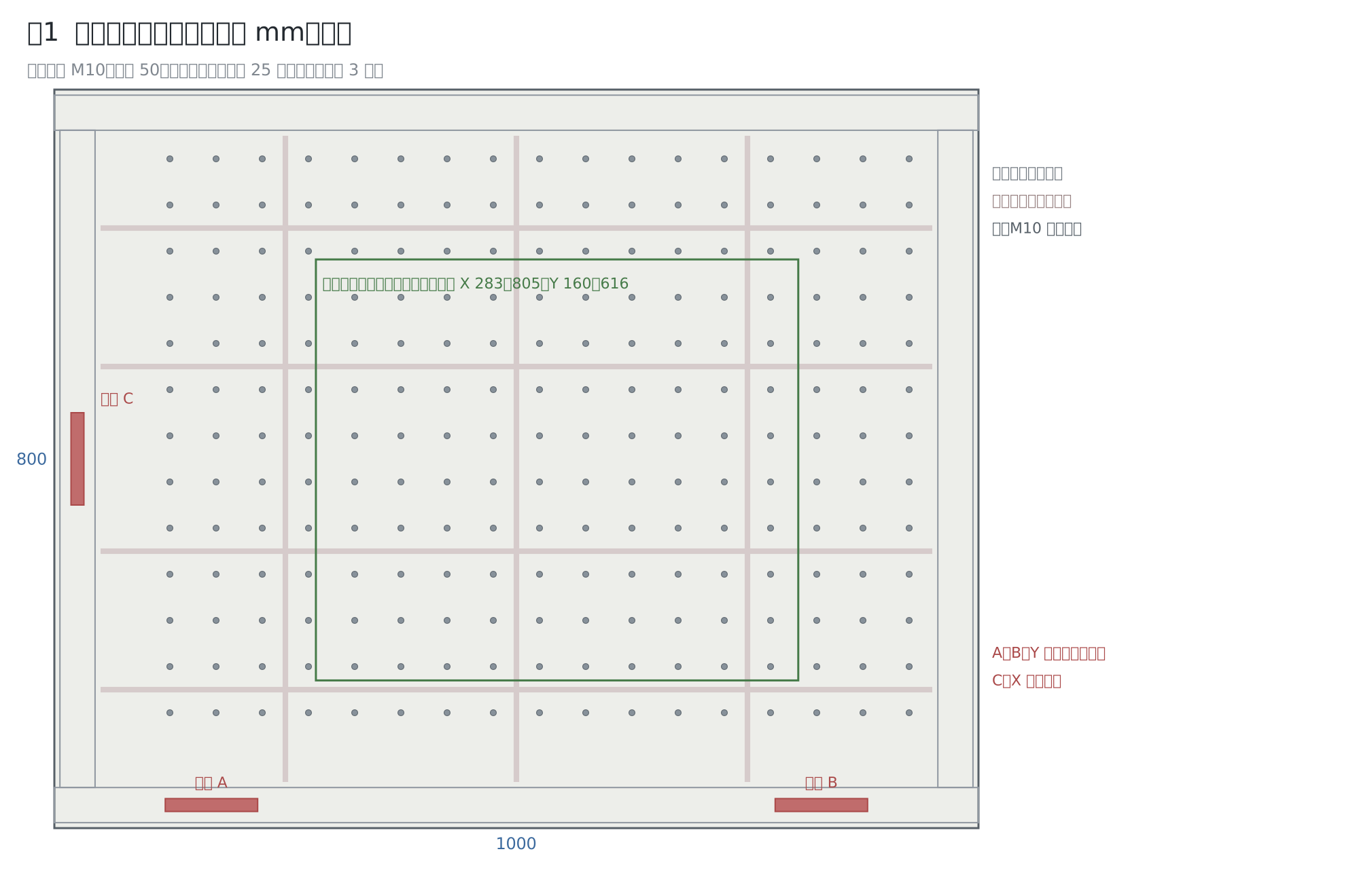
- The tapped holes are M10, with 50 mm spacing, located at 25 + 50n in both X and Y. They do not overlap with the ribs below.
- We drill the holes ourselves on this machine. First, place the machine on the plate and clamp it down, machine the keyways, and then drill the holes within range.
- Since the holes go all the way through, fluid drops below the plate and collects in a pan.
Cross Section
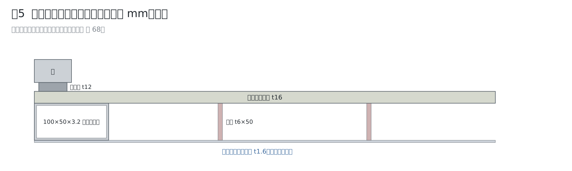
The perimeter uses 100×50×3.2 laid flat, with seven t6×50 ribs. From the top of the plate to the bottom is about 68. We will not add legs, placing it directly on the workbench. Because the workbench is level and cannot provide a slope for fluid, cut notches into the ribs and add a slight slope to the pan, or place a drain at a low corner.
Locating with Keys
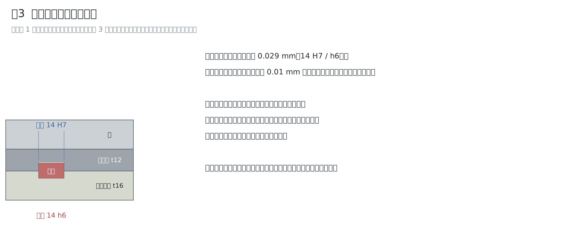
- We decided not to use pins because spacing errors between two holes stack up. Keys determine only the width direction.
- Keys A and B are on the line Y 25 at X 170 and 830. A spacing of 660 establishes the orientation. Key C is on the line X 25 at Y 400.
- The keys are 14 wide, 9 high, and 100 long. The maximum clearance is 0.029 mm (14 H7 / h6). Push against one side before tightening the bolts. Repeatability is expected to be around 0.01 mm, which will be measured in testing.
- For the frame pads, 38×12 flat bar is welded to the underside of the frame and machined together with the rail mounting surfaces. You cannot cut keyways into thin square tubing.
- If you cut the same slots into jigs attached to the workpiece, you can use the keys as they are.
How to Hold the Plate
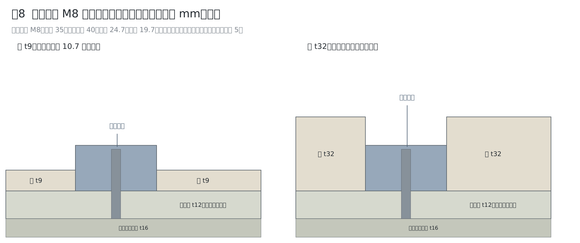
- On top of the tapped plate, secure a t12 sacrificial subplate (about 590×540, about 30 kg) with M10 bolts. The workpiece plate rests directly on this. Through-hole drills may cut slightly into the subplate.
- Because the clamp travels only 5 mm, drill the M8 holes into the subplate on this machine to match the plate size.
- The surface height W matches the thickness of the plate.
Clamp Dimensions (Vendor Table)
| Model | Length (before to after expansion) | Height | Width | Travel |
|---|---|---|---|---|
| M6 | 26.5 to 30.5 | 14.7 | 19.7 | 4 |
| M8 (proposed) | 35 to 40 | 19.7 | 24.7 | 5 |
| M10 | 37 to 42 | 19.7 | 29.7 | 5 |
| M12 | 44 to 49.5 | 24.7 | 29.7 | 5.5 |
Clamping Force Calculation
Bolt axial force F = T / (0.2 d). Clamping force on one side = F / (2 tan(α + φ)). The wedge angle α is estimated from images at 15 to 20° (unverified), friction angle φ = 8.5° (μ 0.15).
| Model | Torque | Axial Force | Clamping Force per Side |
|---|---|---|---|
| M6 | 5 N·m | 4.2 kN | 3.8 to 4.8 kN |
| M8 | 10 N·m | 6.3 kN | 5.8 to 7.2 kN |
| M8 | 20 N·m | 12.5 kN | 11.5 to 14.4 kN |
- For slotting with a lateral force of 200 N, with 4 kN per side, 2 clamps, 2 contact surfaces, and μ 0.15, it can resist up to 2.4 kN. That is about 12 times the required force.
- We chose M8 not for the force, but because its height lets it press higher up on thick plates, and because it is sturdy.
- An end stop held by just a single bolt will slip at about 1 to 2 kN. Mill a step in the subplate to catch it, or support it with two bolts and a key.
- Tightening too much will bow thin plates. Start testing around 10 N·m and check for plate lifting with a dial gauge.
Usable Tool Length
When using the full travel with a spindle end of 120 or higher, W + L − d ≥ 120 (where d is the hole depth). Tools are 125 to 150 mm. The top clearance is 230 − W − L, which with a 150 tool is 71 for t9, and 48 for t32.
Example of Arranging 100×120 Plates
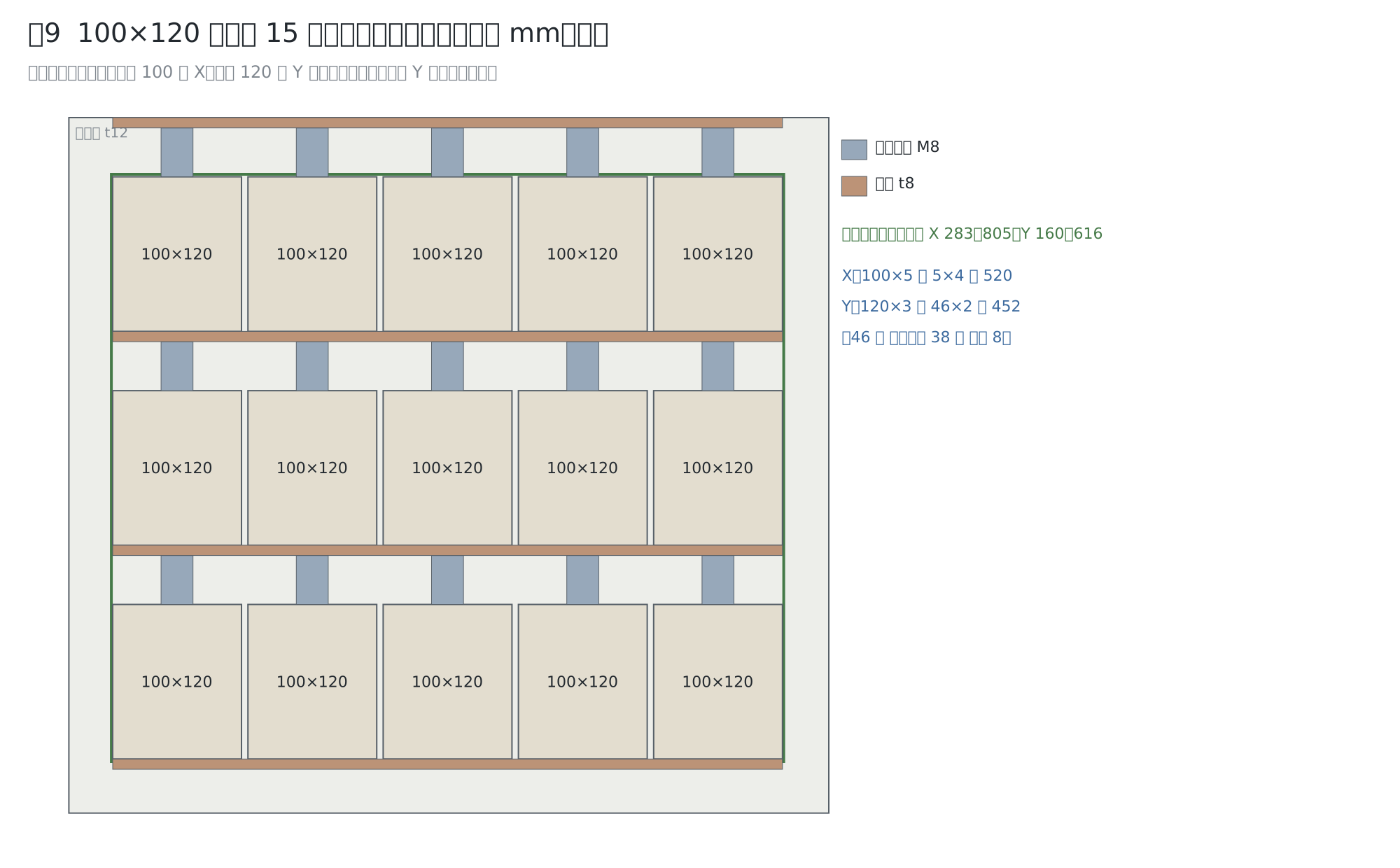
15 plates with the rack attached (18 plates without the rack). The 46 gap in the clamping direction accounts for 38 for the clamp and 8 for the stop. The margins are 2 mm in X and 4 mm in Y, which is not enough if you need to machine the outer profile of the plates. The outermost stops and clamp holes fall outside the spindle range, so drill them by hand or use the M10 tapped holes.
Analysis Results
Tool tip deflection (thrust 1500 N) is 0.039 to 0.044 mm for t9, and about 0.037 mm for t32. For calculations and comparisons of plate deflection, see the Structural Analysis Calculation Sheet.
Open Items
- Actual tightening of the clamps and plate lifting. We will test with 2 units first.
- Flatness of the workbench surface. Welding distortion of the plate. Consider milling only the areas where the pads make contact.
QR code for this page
https://robo100.jp/en/000017
No comments yet.