Bill of Materials and Dimensioned Drawings
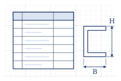
List of parts to fabricate and purchased items. Units are in mm. Dimensions are preliminary; tolerances, weld symbols, and hole locations have not been added yet.
Dimensioned Drawings
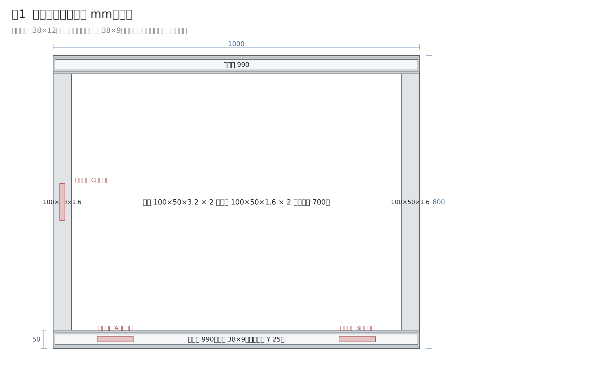
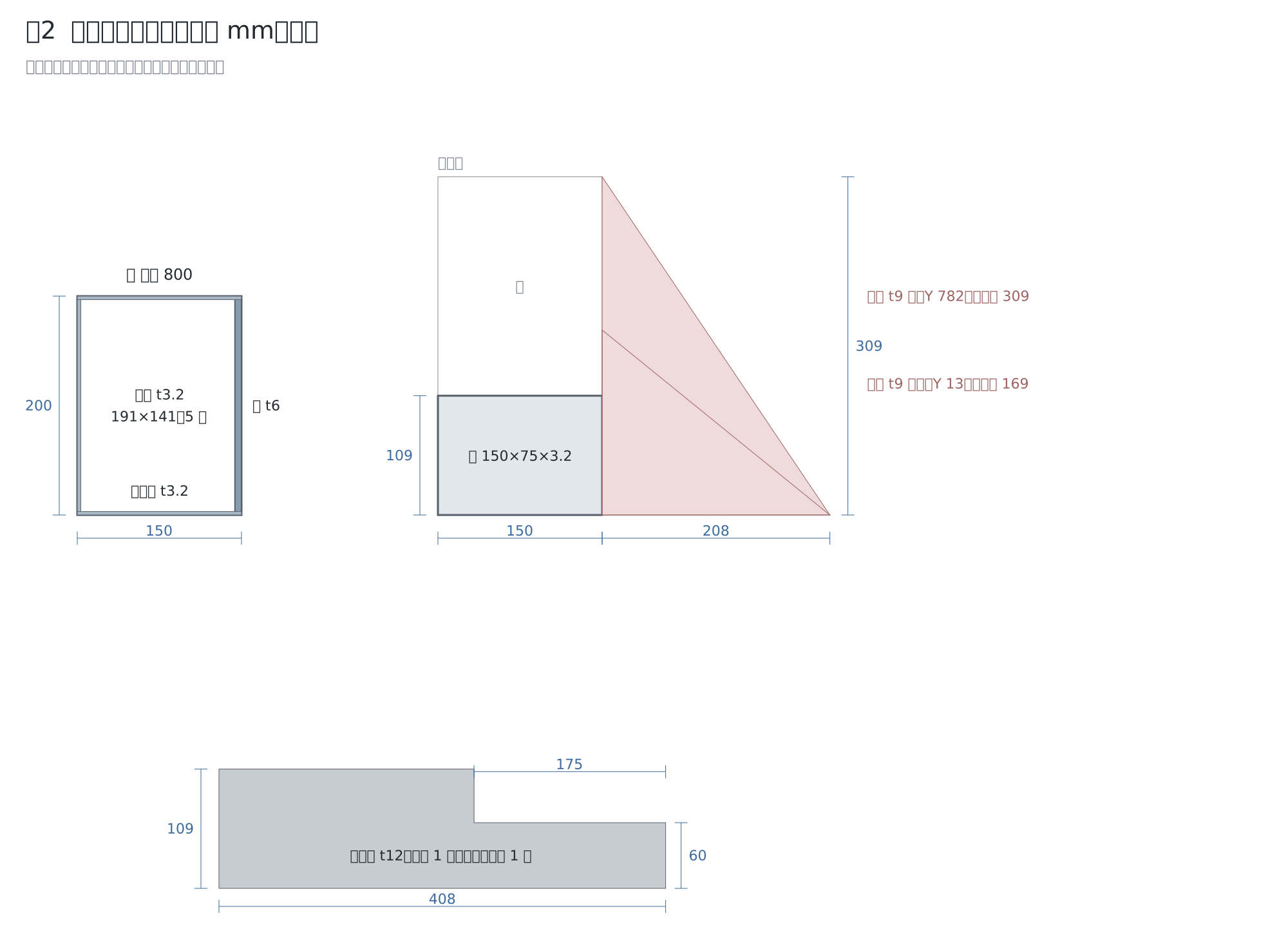
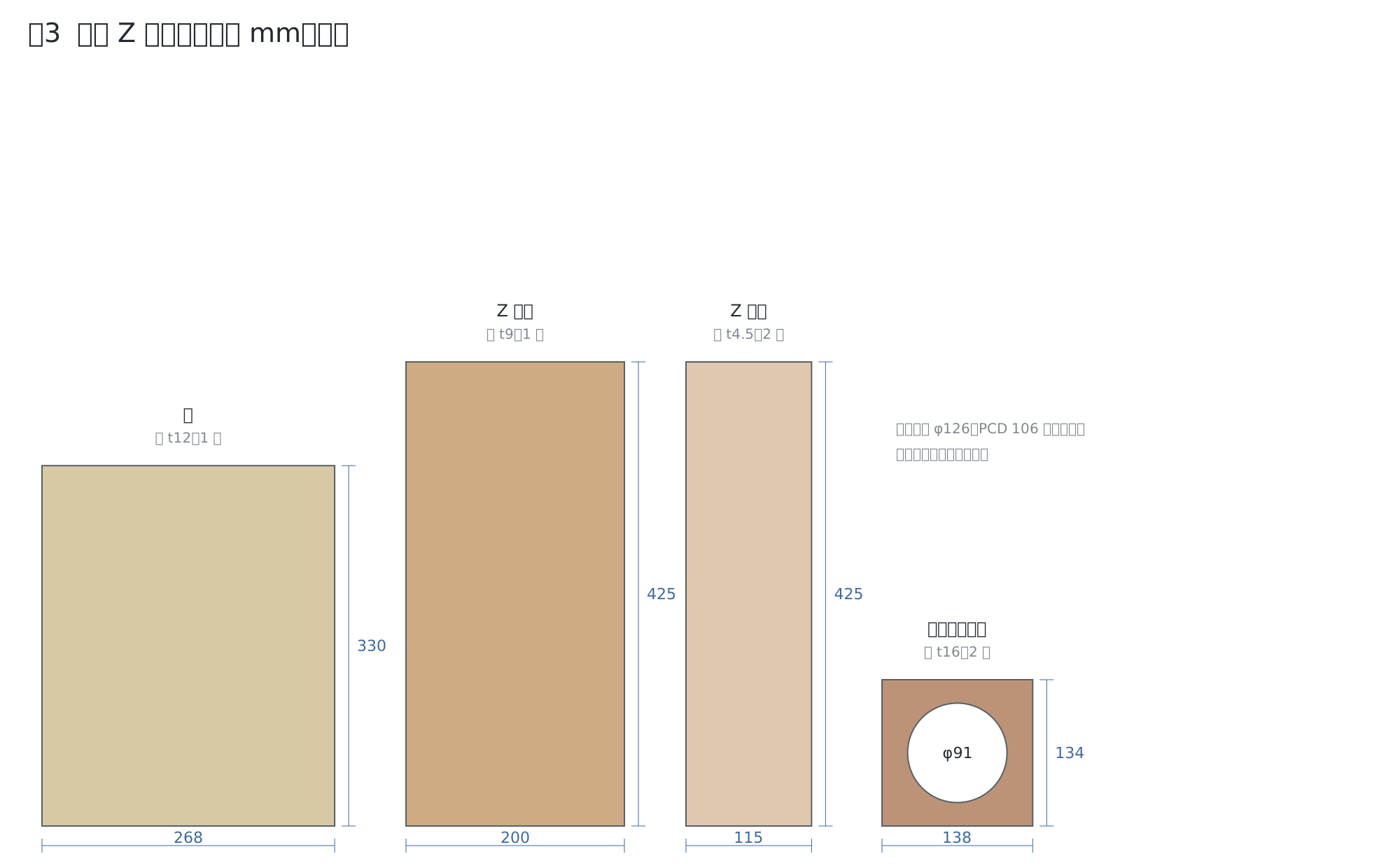
Assembling the beam (installing the bulkheads)
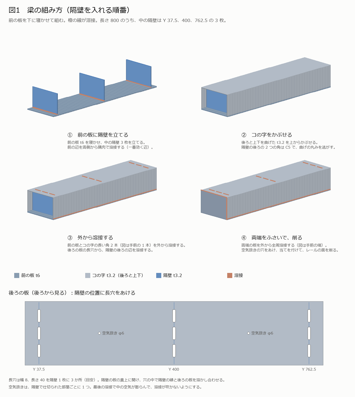
- Lay the front t6 plate flat, and stand the 3 interior bulkheads (Y 37.5, 400, 762.5) up on it. Fillet weld the front edge of the bulkheads along their entire length from both sides.
- Place the bent U-channel t3.2 (forming the back and top/bottom) over them from above. The two rear corners of each bulkhead have a C5 chamfer to clear the inside bend radius.
- Weld the two long outer corners where the front plate meets the U-channel from the outside. Weld the rear edge of the bulkheads through slots cut into the back plate.
- Weld the end plates all the way around from the outside. Before the final weld, drill an air bleed hole (φ6) into each chamber partitioned by the bulkheads.
- Add shims, and machine the rail mounting surface flat.
- The key role of the bulkheads is connecting the front plate and the back plate. If you leave the front edge unwelded, deflection increases by +12% (+22% under 200 N front-to-back load), and leaving the back edge unwelded increases it by +7% (+20%). The top and bottom edges have a smaller effect (+1%, +7%). See Section 6.13 of the Structural Analysis Calculations for the calculations.
- Because the front edge is the most effective and is close to the rail surface, we chose an assembly order that allows continuous welding from both sides instead of welding through slots. If you were to attach the bulkheads to the U-channel first and place the front plate over them afterward, you would have to weld the front edge through slots, which would put slots right on the rail mounting surface.
- A good guideline for the slots is 8 wide and 40 long, in 3 places per bulkhead. Check the size and number of slots with the person doing the welding. Because welding through slots is intermittent, the result falls somewhere between full-length welding and not welding the rear edge at all (the +7% above).
- Welding the bulkheads to the front plate causes the front plate to warp. Make all tack welds first, weld little by little while alternating left/right and front/back, and finally machine the rail mounting surface.
| Section | Part | Dimensions | Qty |
|---|---|---|---|
| Frame | Longitudinal | Square tube 100×50×3.2, L1000 | 2 |
| End | Square tube 100×50×1.6, L700 | 2 | |
| Seat (keyway) | Flat bar 38×12, L1000 | 2 | |
| Seat | Flat bar 38×12, L712 | 2 | |
| Backing strip (rail) | Flat bar 38×9, L1000 | 2 | |
| Gantry | Beam front | t6, 200×800 | 1 |
| Beam channel | t3.2, flat pattern approx. 500×800 | 1 | |
| Bulkhead | t3.2, 191×141 | 5 | |
| Leg | 150×75×3.2, H109 | 2 | |
| Rib (far side) | t9, 208×309 triangle (up to beam top face) | 1 | |
| Rib (near side) | t9, 208×169 triangle (up to 60 above beam bottom face) | 1 | |
| Foot plate | t12, L-shape 408×109 | 2 | |
| Nut bracket | t12, 48×50 | 2 | |
| Backing strip (Y rail) | Flat bar 38×9, L740 | 2 | |
| Bed | Bed | Steel t12, 268×330 | 1 |
| Z | Z plate | t9, 200×425 | 1 |
| Z wall | t4.5, 115×425 | 2 | |
| Head bracket | t16, 138×134, φ91 hole | 2 | |
| Spindle motor bracket | Around t6, unfinalized design | 1 | |
| Cover | Around t1.6 | 1 |
Fabricated Parts (Base and Rack)
| Part | Dimensions | Qty |
|---|---|---|
| Tapped plate | t16, 1000×800 | 1 |
| Perimeter | Square tube 100×50×3.2 laid flat, L1000 and L600 | 2 each |
| Rib | t6×50, L800 | 4 |
| Rib | t6×50, L600 | 3 |
| Fluid tray | t1.6, approx. 900×700 | 1 |
| Key | 14×9×100 (14 h6) | 3 |
| Subplate | t12, approx. 590×540 | 1 |
| Stop bar | t8, L520 | 4 |
| Support bar | Flat bar 38×12, L570 | 1 |
| Post | Flat bar approx. 38×12, H112 | 2 |
| Holder nest | Profile gripping holder groove, unfinalized design | 5 |
Purchased Items by Axis
| Axis | Rails | Blocks | Total Screw Length | Motor | Pulleys | Belt (Calculated) |
|---|---|---|---|---|---|---|
| X (2 sets) | 990×2 | 4 | Approx. 870×2 | 1-CL57Y-S30-V20×2 | 40T, 20T | Approx. 265-5M |
| Y | 730×2 | 4 | Approx. 755 | 1-CL57Y-S30-V20 | 40T, 20T | Approx. 450-5M |
| Z | 425×2 | 4 | Approx. 380 | 34HS45-6004D-E1000-B700 | 32T, 16T | Approx. 225-5M |
| Spindle | A6-RS1000H2A1-M17 | 25T, 50T on head | Approx. 425-5M |
- Belt pitch length: L = 2C + π(D + d)/2 + (D − d)²/4C. C is 55 for X, 148.5 for Y, 50 for Z, and 115 for the spindle. Adjust center-to-center distance to match standard pitch lengths.
- Rails are LRXDG30 (on hand). DFU1605 on each axis, with fixed-side BK12 and supported-side BF12. Make a custom bracket for the Z nut.
- Make the Y screw length extend 15 beyond the supported-side bearing (BF12) so it does not hit the rear rib. Verify end-machining dimensions when ordering.
- A 16T pulley on Z is small for a φ14 bore. Check whether one can be purchased.
- M8 wedge clamps: Depends on the number of plates. 15 pieces for fifteen 100×120 plates.
QR code for this page
https://robo100.jp/en/000018
No comments yet.