Structural Analysis Report (CalculiX)
A calculation report examining the stiffness of the ROBO100 frame using the finite element method. Sections 1 to 5 summarize the current design, and Section 6 records the investigations leading up to it. Units are in mm. Values indicate the deflection at the tool tip, with forces and directions based on "Terminology and Coordinates" in Section 7. All values are calculated and unverified on the actual machine.
1. Conclusions
- In the current design, the fore-and-aft deflection of the tool tip against a drilling force of 1500 N is 0.033 mm (table surface height 0, tool 150, without stand). On a plate on top of the stand, it is 0.031 to 0.039 mm. Against a side force of 200 N, it is 0.026 mm (fore-and-aft) and 0.028 mm (lateral).
- About 61% of the deflection comes from the linear guides. The guide stiffness is assumed to be 200 N/µm; if it is 100, the deflection is 0.049 mm, and if 400, it is 0.025 mm. We will measure the guides on the actual machine to verify this.
- The decisions that were effective, in order of impact, are: making Z into a box, adding ribs to the legs, adding bulkheads to the beam, shortening the legs to use the spindle closer to the beam, extending the ribs to the front face of the beam, using two head brackets, and widening the Y-rail spacing (Section 3).
- We reduced weight by thinning the plates that have little effect. Lightening holes and building the beam out of square tubing are not worth the trouble (Section 4).
- Strength is more than adequate. The maximum stress is 6 MPa, which is 1/40 of the yield point of steel (SS400), 245 MPa. Plate thickness is determined by deflection, not strength.
- What determines hole positioning accuracy is lead screw error rather than deflection (Machining Methods for Accurate Holes).
2. Current Design
Shapes and dimensions are in Machine Shape and Dimensions, and parts are in the Parts List and Dimension Drawings. Here, we list only the parts relevant to stiffness.
| Part | Configuration |
|---|---|
| Frame | Square tubing 100×50. Longitudinal t3.2, ends t1.6 |
| Legs | Square tubing 150×75×3.2, height 109. Foot plate t12 underneath |
| Ribs | t9. Extending from the front face of the legs along the front face of the beam. Back reaches the top surface of the beam (height 309), front reaches under the Y belt cover (height 169) |
| Beam | Assembled from bent plates, 200×150, length 800. Front t6, others t3.2. Five bulkheads t3.2 (including both ends) |
| Y guides | Rail spacing 170 |
| Table | Steel t12 |
| Z box | Z plate t9, side walls t4.5 (depth 120). Front is a cover |
| Head brackets | t16, 2 plates (top and bottom), spacing 280 |
| Frame weight | 74.7 kg (analysis model; whole machine is about 189 kg) |
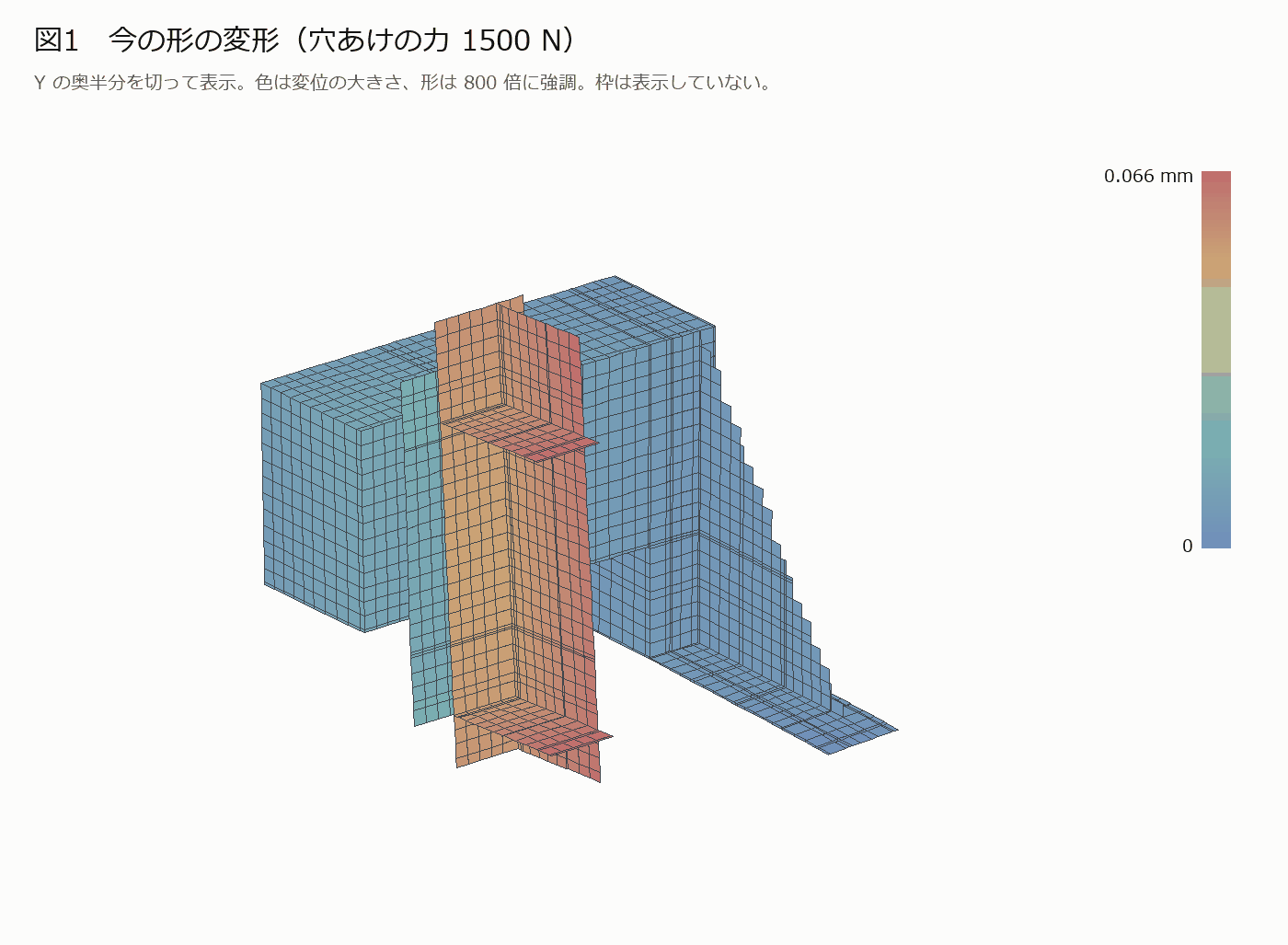
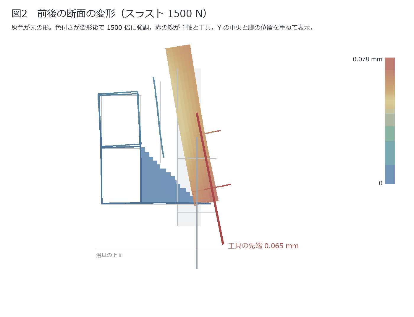
When the spindle is pushed upward by the drilling force, the Z box tilts forward, the beam twists, and the base of the legs bends. The areas with large deflection are the Z box and the guides; within the frame itself, they are the beam and the base of the legs.
3. Design Decisions and Their Effectiveness
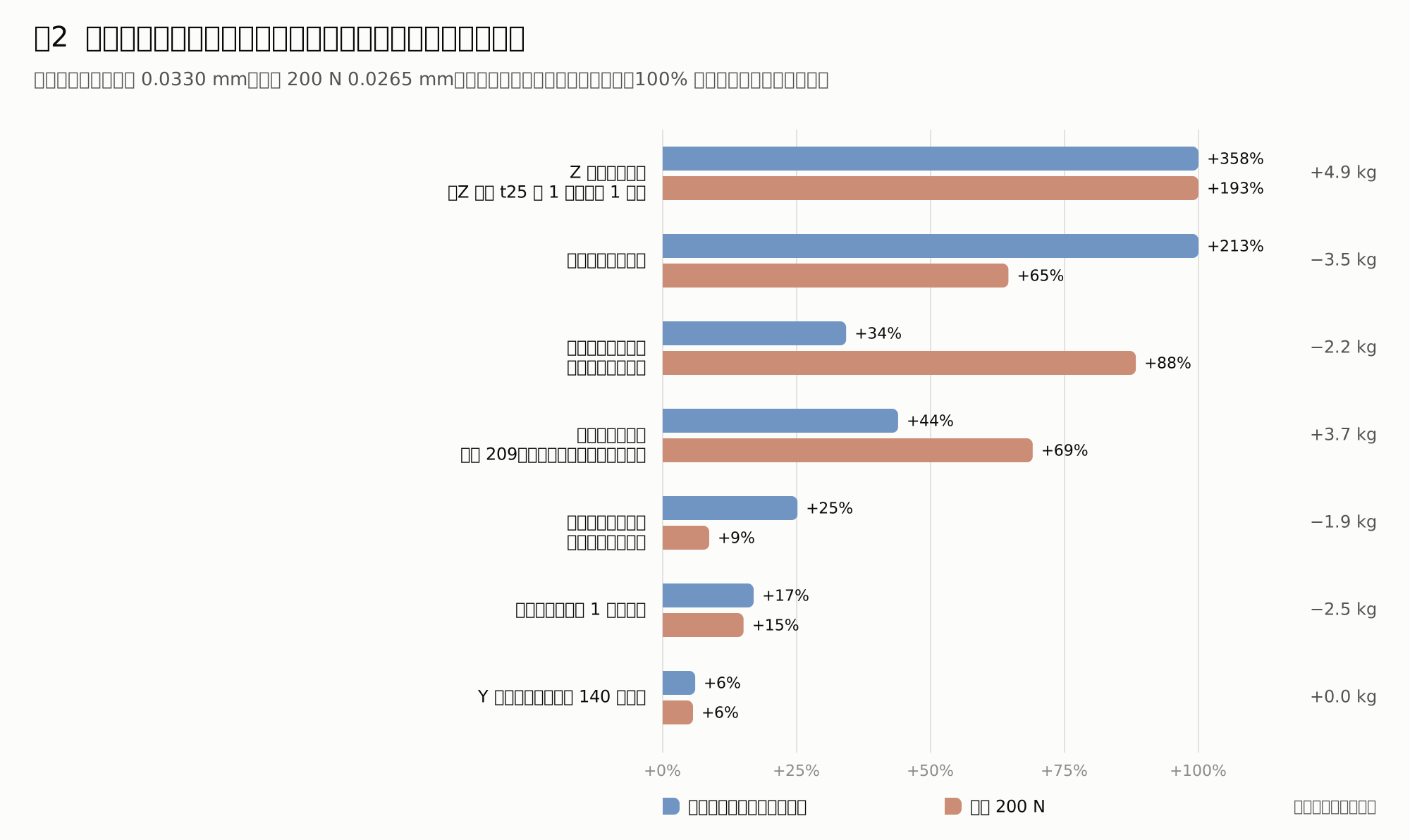
Starting from the current design, we solved the model with only one decision reverted at a time. Since all other conditions are kept identical, the increase in deflection represents the effectiveness of that decision. Conditions: table surface height 0, tool 150, without stand.
| Decision | When Reverted | Tip Fore-and-Aft | Fore-and-Aft 200 N | Weight kg | Record |
|---|---|---|---|---|---|
| Current design | ― | 0.0330 | 0.0265 | 74.7 | |
| Make Z into a box (Z plate with 2 side walls, 2 head brackets) | Single Z plate t25, 1 bracket | 0.1510 (+358%) | 0.0777 (+193%) | +4.9 | 6.2 |
| Add ribs to legs | Without ribs | 0.1032 (+213%) | 0.0436 (+65%) | −3.5 | 6.4 |
| Add bulkheads to beam | End plates only | 0.0443 (+34%) | 0.0499 (+88%) | −2.2 | 6.12 |
| Shorten legs and use spindle close to beam | Legs 209 | 0.0475 (+44%) | 0.0448 (+69%) | +3.7 | 6.4 |
| Extend ribs to front face of beam | Up to bottom surface of beam | 0.0413 (+25%) | 0.0288 (+9%) | −1.9 | 6.10 |
| Use 2 head brackets (top and bottom) | 1 bracket | 0.0386 (+17%) | 0.0305 (+15%) | −2.5 | 6.2, 6.12 |
| Set Y-rail spacing to 170 | Spacing 140 | 0.0350 (+6%) | 0.0280 (+6%) | 0 | 6.2 |
The difference in weight shows whether it increases (+) or decreases (−) when reverted. The ribs, bulkheads, and brackets weigh just a few kg, yet they reduce deflection significantly.
Decisions Made for Weight Reduction
| Decision | When Reverted | Tip Fore-and-Aft | Fore-and-Aft 200 N | Weight kg | Record |
|---|---|---|---|---|---|
| Thin down ineffective plates (frame ends t1.6, bulkheads t3.2, Z side walls t4.5, brackets t16, foot plates t12) | Original thicknesses (2.3, 4.5, 6, 20, 16) | 0.0321 (−3%) | 0.0258 (−3%) | +8.1 | 6.8, 6.10 |
| Make table steel t12 (do not machine aluminum) | Aluminum t25 | 0.0316 (−4%) | 0.0255 (−4%) | −2.3 | 6.7 |
Thinning the plates saved 8.1 kg, and the increase in deflection was held to +3%. That difference was recovered by extending the ribs.
4. Alternatives Not Adopted
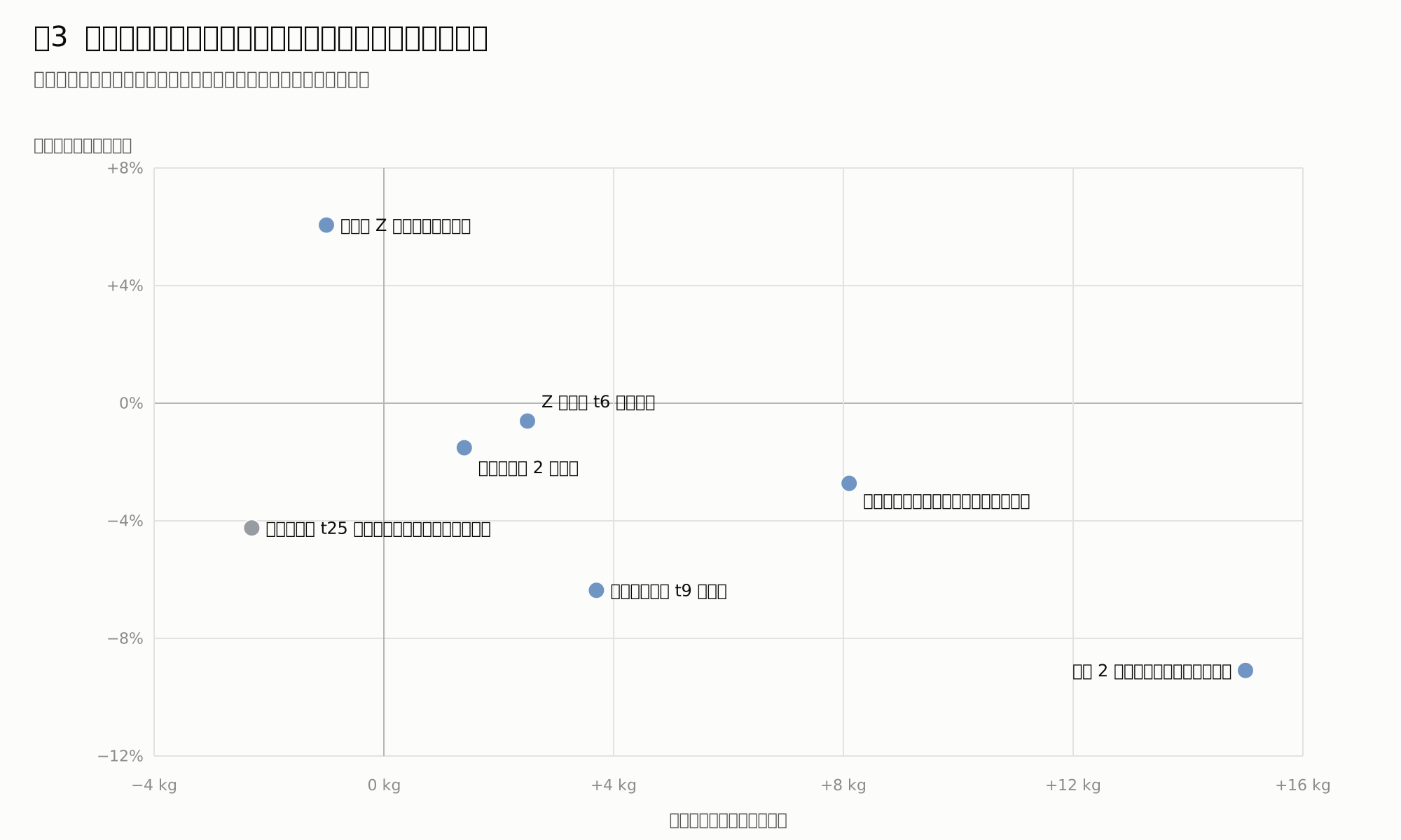
These were solved by adding to or replacing parts in the current design. Closer to the bottom left is better (lighter, with less deflection).
| Option | Tip Fore-and-Aft | Fore-and-Aft 200 N | Weight kg | Reason Not Adopted | Record |
|---|---|---|---|---|---|
| Make front plate of beam t9 | 0.0309 (−6%) | 0.0256 (−3%) | +3.7 | Effective, but heavy. The first thing to consider if we want even more stiffness | 6.8 |
| Add 2 bulkheads to beam | 0.0325 (−2%) | 0.0257 (−3%) | +1.4 | Small effect | 6.9 |
| Add Z front plate t6 | 0.0328 (−1%) | 0.0264 (0%) | +2.5 | Hardly any effect. We will make the front a cover | 6.6 |
| Lightening holes in bulkheads and Z side walls | 0.0350 (+6%) | 0.0289 (+9%) | −1.0 | Deflection increases too much for the amount of weight saved | 6.8 |
| Build beam from two square tubes and flat steel bars | 0.0300 (−9%) | 0.0256 (−3%) | +15.0 | Effective, but 15 kg heavier | 6.9 |
In addition to these, in Section 6.1 of the records, we compared and decided against building the frame from channel steel (either too heavy or too soft), and in Section 6.2, using 3 blocks on each side for Z (effective laterally, but risks the table hitting the ribs) and using a φ20 screw for Z (reduces vertical deflection only).
5. Detailed Results for the Current Design
Spindle Height and Guide Stiffness (Tool 150, Without Stand)
| Condition | Tip fore/aft | Tip up/down | Fore/aft 200 N | Left/right 200 N |
|---|---|---|---|---|
| Surface height 0 | 0.033 | 0.058 | 0.026 | 0.028 |
| Surface height 50 | 0.029 | 0.058 | 0.021 | 0.025 |
| Spindle at top | 0.027 | 0.058 | 0.018 | 0.023 |
| Spindle at bottom | 0.043 | 0.058 | 0.040 | 0.035 |
| Guide 100 N/µm | 0.049 | 0.065 | 0.039 | 0.039 |
| Guide 400 N/µm | 0.025 | 0.054 | 0.020 | 0.022 |
The higher the spindle is raised and the closer it is used to the Z blocks, the smaller the deflection. Guide stiffness is an assumed value, so we will measure it on the actual machine.
Machining a plate on the stand
Stand height is 50, with the plate placed on a shim plate. Values are the relative displacement between the tool tip and the plate. t32 was solved with W 31.
| Plate | Tool | Tip fore/aft | Tip up/down | Fore/aft 200 N | Left/right 200 N |
|---|---|---|---|---|---|
| t9 (W 6) | 150 | 0.033 | 0.136 | 0.026 | 0.029 |
| t9 (W 6) | 130 | 0.039 | 0.138 | 0.031 | 0.030 |
| t32 (W 31) | 150 | 0.032 | 0.136 | 0.024 | 0.027 |
| t32 (W 31) | 130 | 0.031 | 0.136 | 0.024 | 0.027 |
Up/down values include the deflection of the stand plate (when the underside is supported at only 12 points). It is expected to be smaller once mounted on a workbench. It doesn't affect through-holes.
Natural frequencies
At surface height 0: 71, 99, 117, 162, and 202 Hz. Avoid spindle speeds close to the tooth pass frequency. For a 2-flute cutter, 71 Hz corresponds to about 2150 rpm.
Stress
Maximum von Mises stress is 6.2 MPa (legs) under a 1500 N drilling thrust, 1.7 MPa under 200 N fore/aft, and 2.6 MPa under 200 N left/right. These are well below the yield point of steel (245 MPa). Corner values change depending on element size and weld shape, so treat them as rough guides.
Effect by component
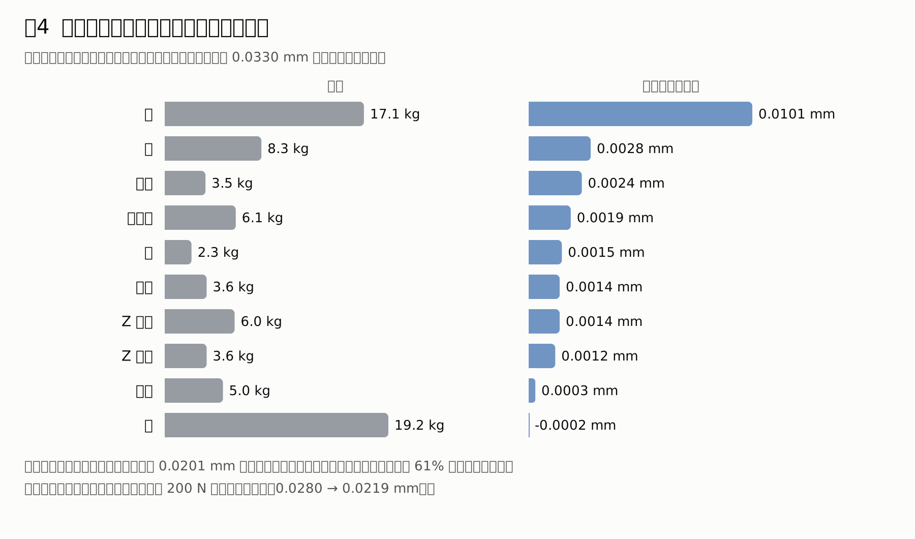
In the framework, the beam has the largest effect. The heavy base frame has almost no effect on fore/aft displacement.
6. Record of design studies
The studies leading up to the current design. "Current proposal" or "baseline" in each section refers to the geometry at that point. Values were solved with the design as it stood then, so conditions differ from the values in sections 1–5. Only compare values within the same table.
| Section | What was changed | What we learned |
|---|---|---|
| 6.1 | Framework members (square tubing, channel, bent-and-assembled sheet) | A beam made of bent-and-assembled sheet (Proposal G) is the lightest for the same stiffness as square tubing |
| 6.2 | Z section (wall depth, front plate, mount spacing, number of blocks, leadscrew, Y rail spacing) | We adopted a wall depth of 120, mount spacing of 280, and Y rail spacing of 170. Guide stiffness has the largest effect |
| 6.3 | Combinations of 6.1 and 6.2 | Using the spindle raised higher reduces fore/aft displacement |
| 6.4 | Leg length | Shorten the legs to use the spindle closer to the beam. We adopted legs 105 (now 109 to account for thinner foot plates) |
| 6.5 | Stand height and plate ribs | Stand height only affects plate deflection (up/down). We adopted height 50 |
| 6.6 | Z front plate | Almost no effect. We'll use it as a cover |
| 6.7 | Base material | We adopted steel t12 (we won't machine aluminum) |
| 6.8 | Lightening holes and plate thickness | Lightening holes aren't worth the effort. Thinned the plates that don't do much |
| 6.9 | Making the beam from two square tubes and flat bar | Doesn't end up lighter and stiffer than the current sheet-metal box |
| 6.10 | Extending ribs to the front face of the beam | Very effective. Combined with the plate thicknesses from 6.8, we adopted Light 7, which became the current design |
| 6.11 | Results before adding Light 7 (N1) | Kept as a baseline for comparison with section 3 |
| 6.12 | Effect by member (geometry before fixing leg design) | The guides, beam, and Z walls/plates are effective. Without bulkheads, displacement under fore/aft 200 N increases substantially |
| 6.13 | Which edges to weld for bulkheads inside the beam | The front and rear edges are effective. The top and bottom edges have little effect. Decided on assembly method |
| 6.14 | Left/right position of leg ribs (outer edge, center, inner edge of square tube) | Differences are small as long as they are above the X blocks. Pushing to the outer edge is slightly worse. Kept in the current position |
| 6.15 | Shifting legs and ribs toward the center of the X blocks (beam 825) | Moving the legs makes no difference. Ribs give −2%, but at the expense of Y travel and width. Kept as the current design |
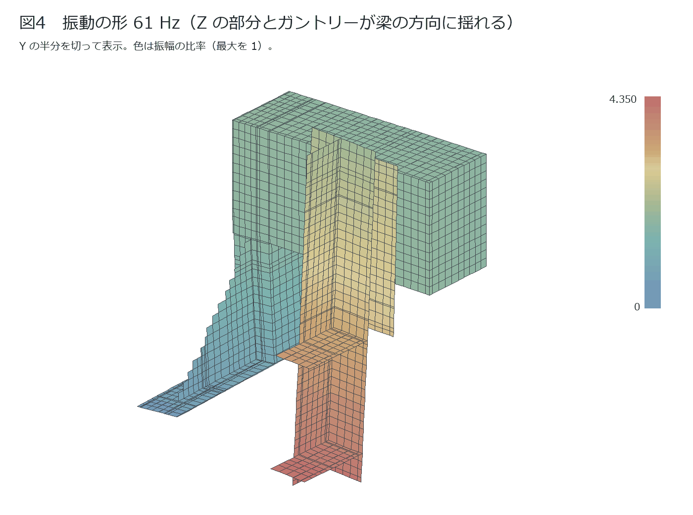
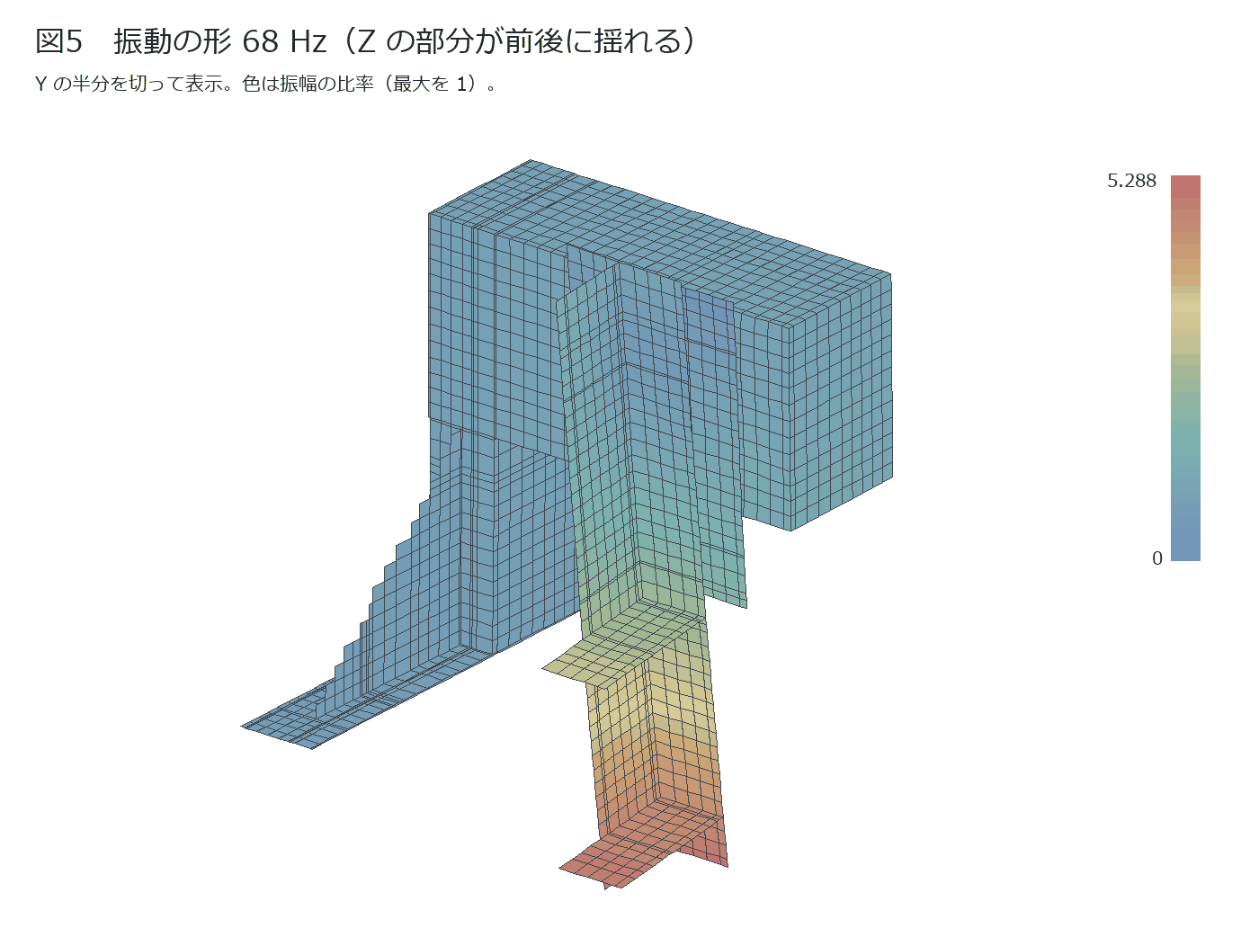
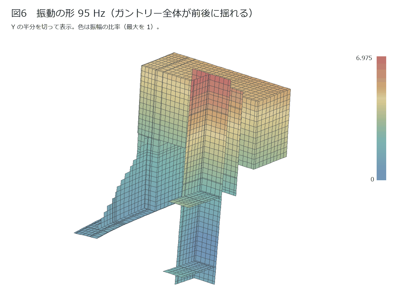
All deformation plots use the same scale factor (3D: 500x, cross section: 800x) and color map (red for 0.10 mm or more). The stepped edges of the ribs are an artifact of the mesh shape, not the real part profile.
6.1 Framework proposals
The Z section is shared; only the framework was changed. The spindle is at the bottom (spindle nose 130, legs 205).
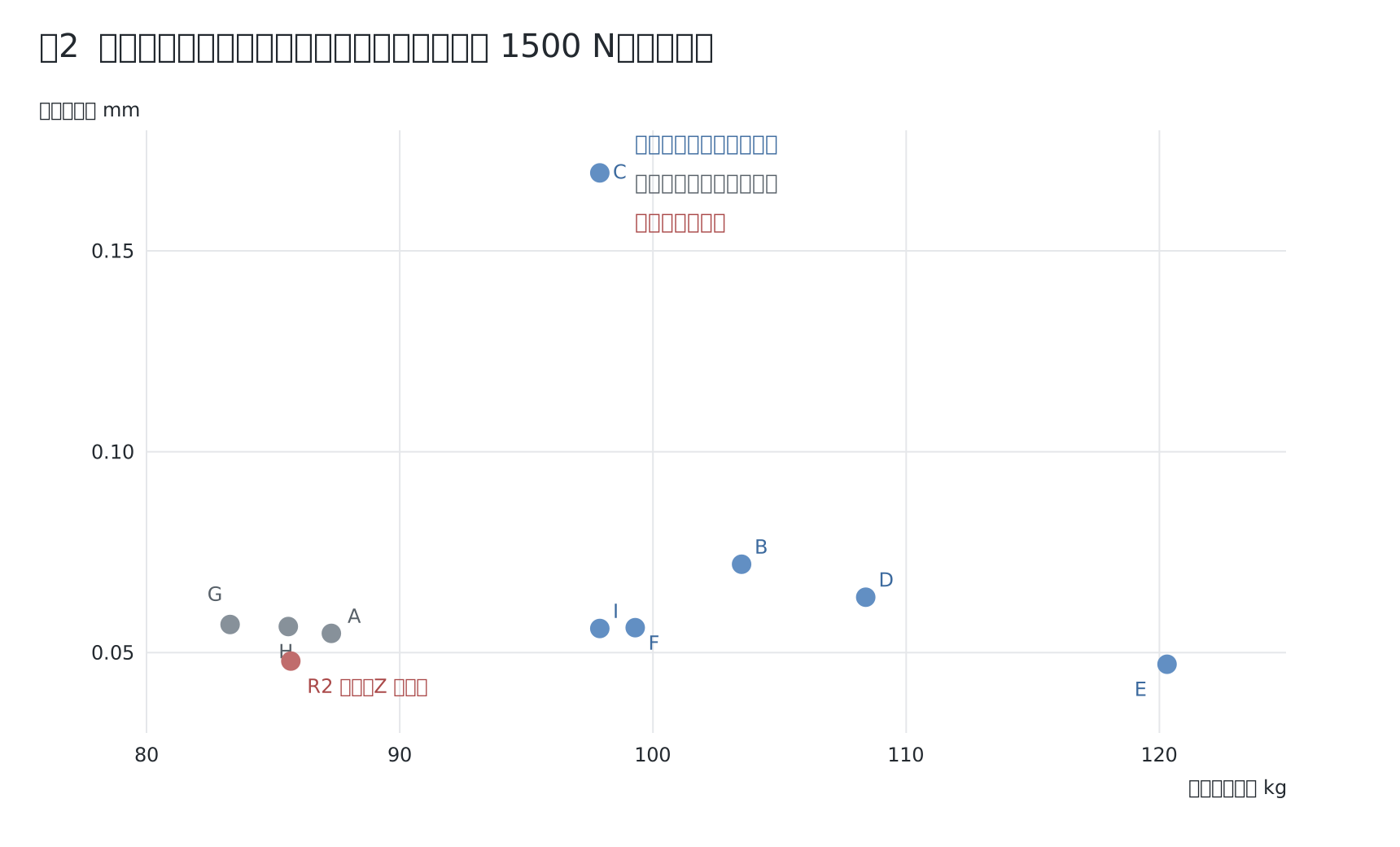
| Plan | Details | Tip, front-back | Tip, up-down | Front-back 200 N | Left-right 200 N | Model kg | Verdict |
|---|---|---|---|---|---|---|---|
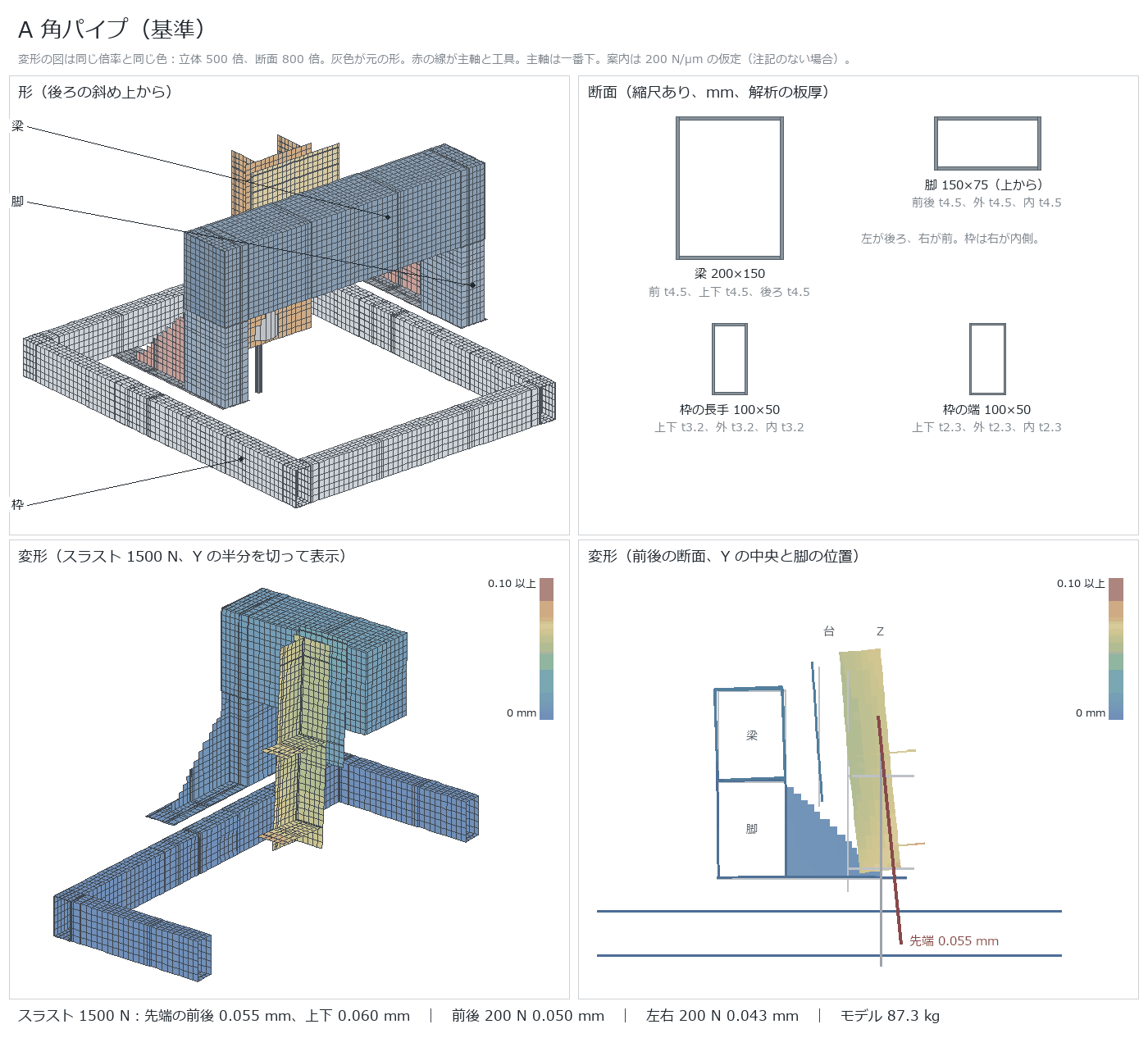
| A | Square tubing. Beam 200×150×4.5, legs 150×75×4.5, frame t3.2 | 0.055 | 0.060 | 0.050 | 0.043 | 87.3 | Baseline. Can be built from standard square tubing |
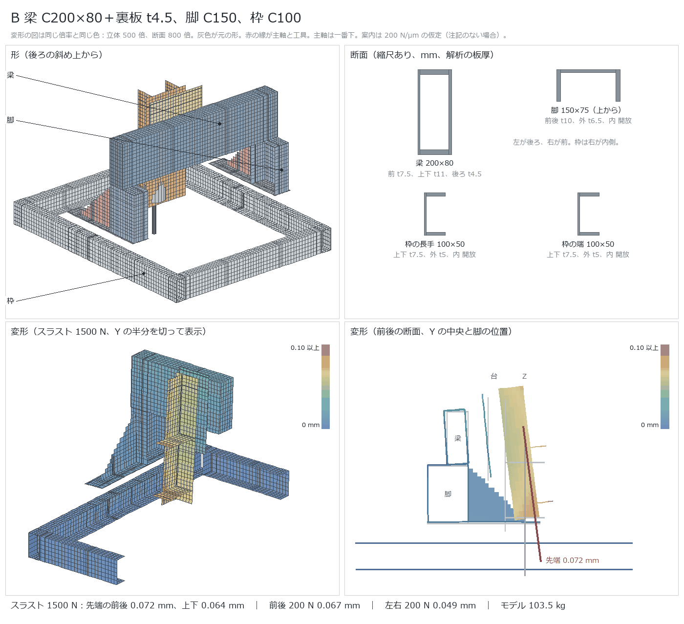
| B | Beam C200×80 with t4.5 back plate, legs C150, frame C100 | 0.072 | 0.064 | 0.067 | 0.049 | 103.5 | Shallow depth, flexible and heavy |
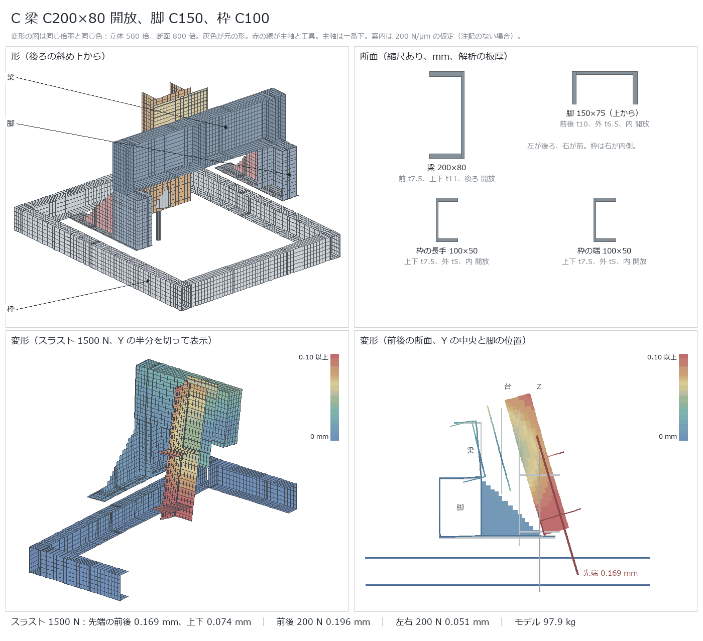
| C | Beam C200×80 left open, legs C150, frame C100 | 0.169 | 0.074 | 0.196 | 0.051 | 97.9 | Open cross section is weak against torsion, deformation is by far the largest. Unusable |
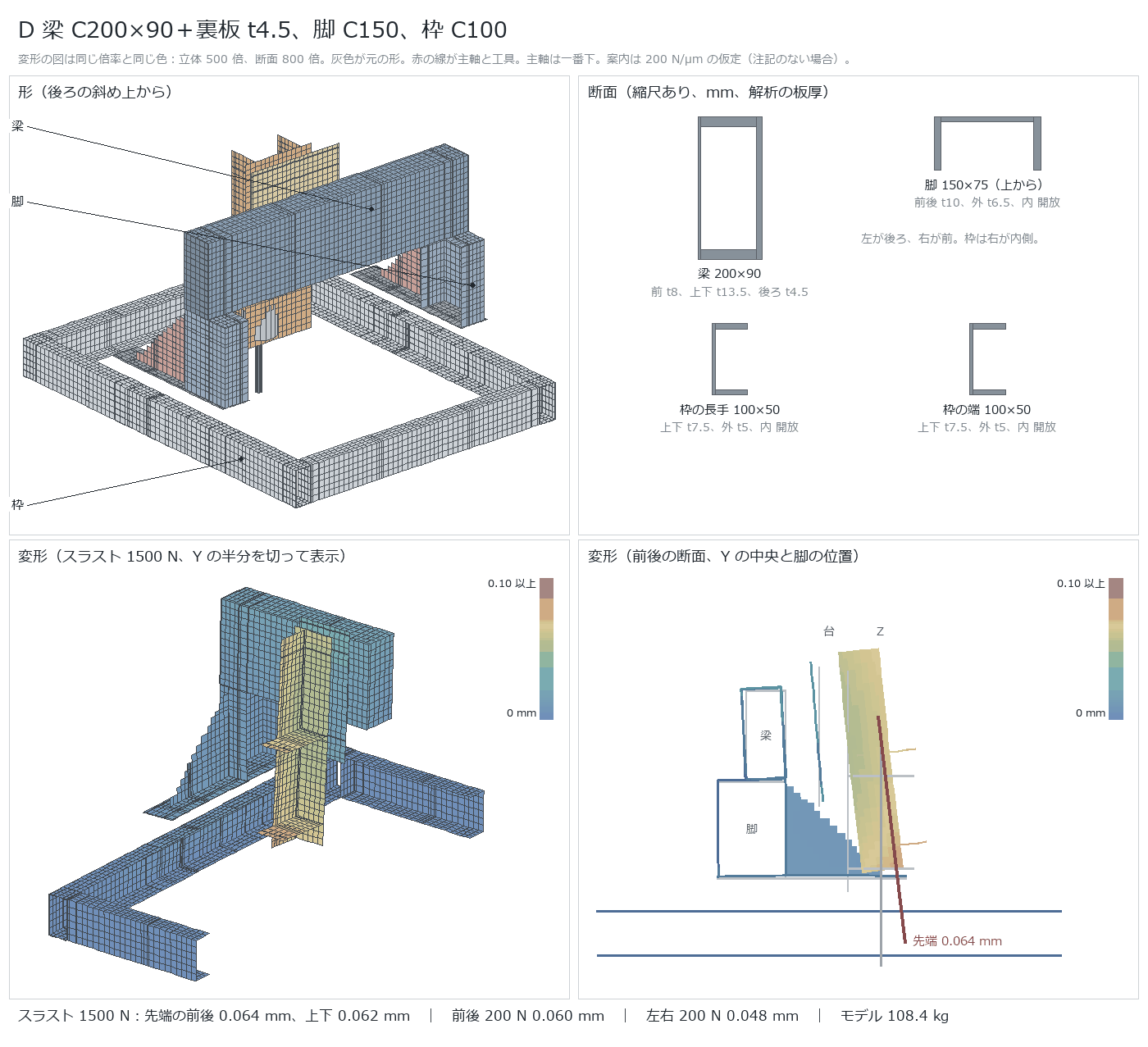
| D | Beam C200×90 with t4.5 back plate, legs C150, frame C100 | 0.064 | 0.062 | 0.060 | 0.048 | 108.4 | Stiffer than B, but falls short of A and is heavy |
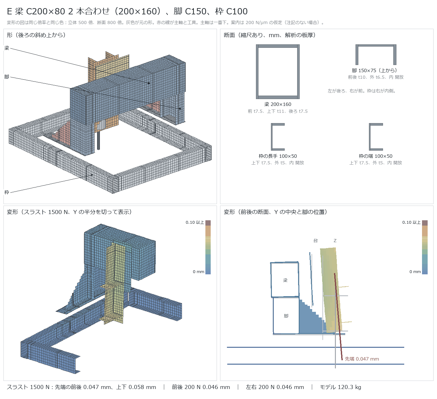
| E | Two C200×80 beams joined, legs C150, frame C100 | 0.047 | 0.058 | 0.046 | 0.046 | 120.3 | Stiffest, but 33 kg heavier |
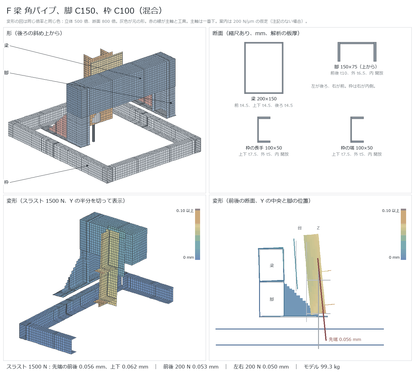
| F | Beam is square tubing, legs C150, frame C100 | 0.056 | 0.063 | 0.053 | 0.050 | 99.3 | Nearly the same stiffness as A, but 12 kg heavier |
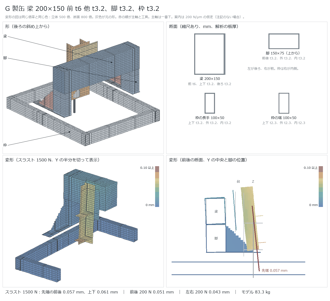
| G | Bent-sheet assembly. Beam 200×150 front t6 others t3.2, legs t3.2 | 0.057 | 0.061 | 0.051 | 0.043 | 83.3 | Nearly the same stiffness as A, and 4 kg lighter. Adopted |
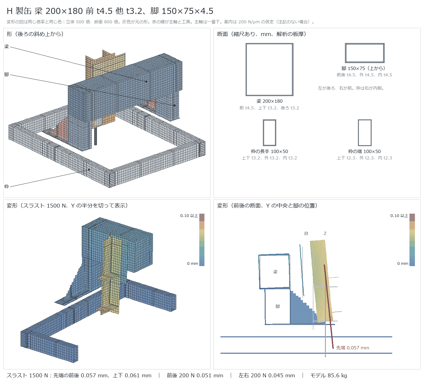
| H | Bent-sheet assembly. Beam 200×180 front t4.5 others t3.2 | 0.057 | 0.061 | 0.051 | 0.045 | 85.6 | Same stiffness as G, but 2.3 kg heavier |
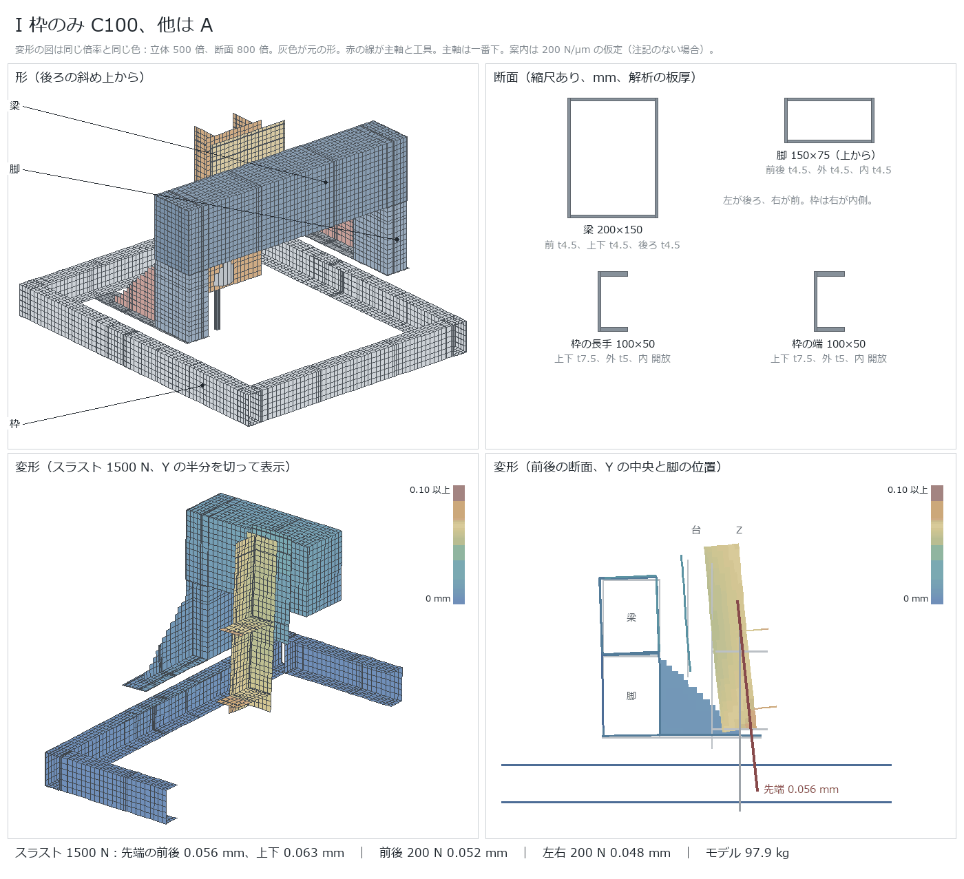
| I | Frame only C100, others same as A | 0.056 | 0.063 | 0.052 | 0.048 | 97.9 | Stiffness is the same, but 10.6 kg heavier |
Plan A: Square tubing. Beam 200×150×4.5, legs 150×75×4.5, frame t3.2
Plan B: Beam C200×80 with t4.5 back plate, legs C150, frame C100
Plan C: Beam C200×80 left open, legs C150, frame C100
Plan D: Beam C200×90 with t4.5 back plate, legs C150, frame C100
Plan E: Two C200×80 beams joined, legs C150, frame C100
Plan F: Beam is square tubing, legs C150, frame C100
Plan G: Bent-sheet assembly. Beam 200×150 front t6 others t3.2, legs t3.2
Plan H: Bent-sheet assembly. Beam 200×180 front t4.5 others t3.2
Plan I: Frame only C100, others same as A
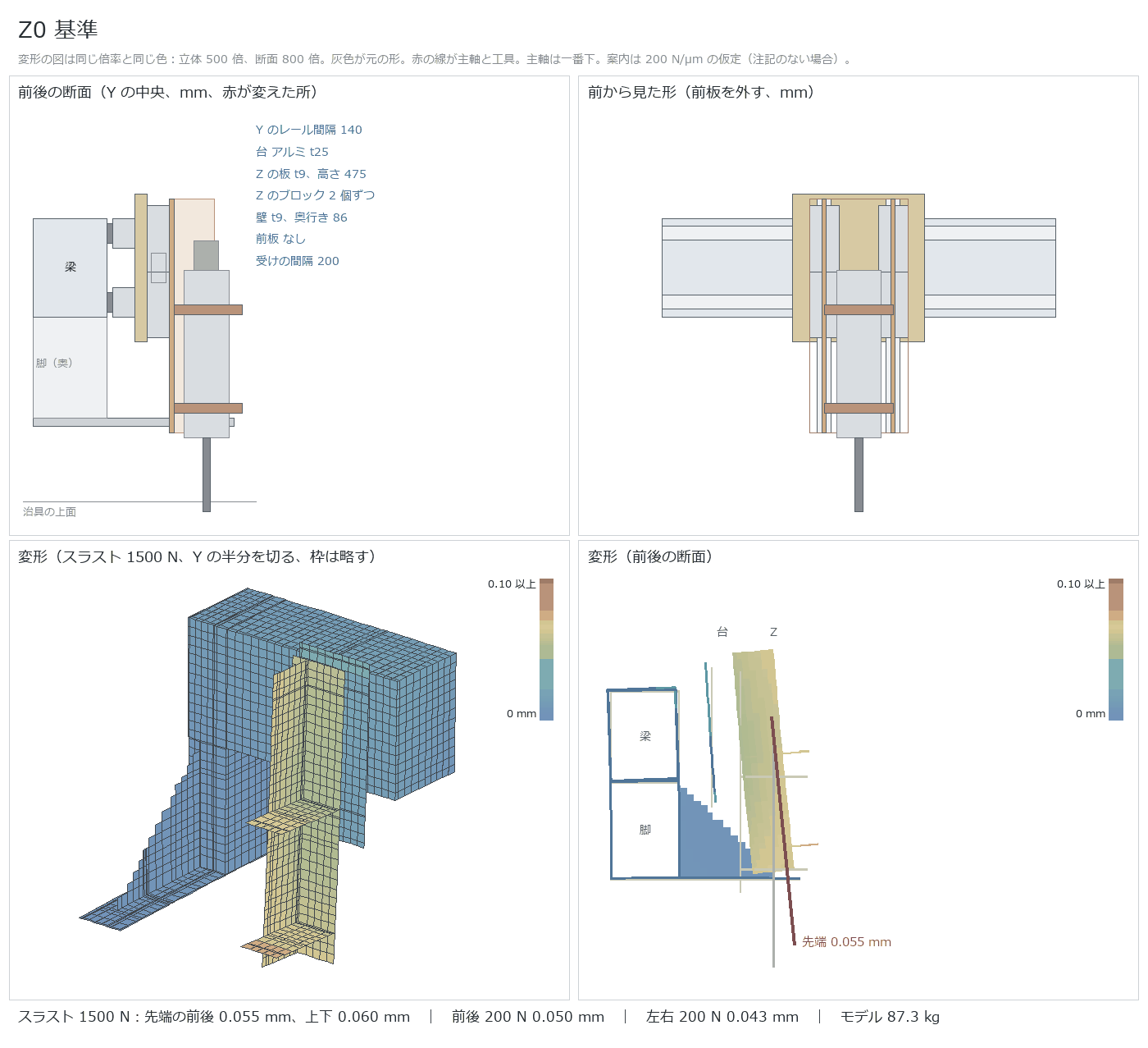
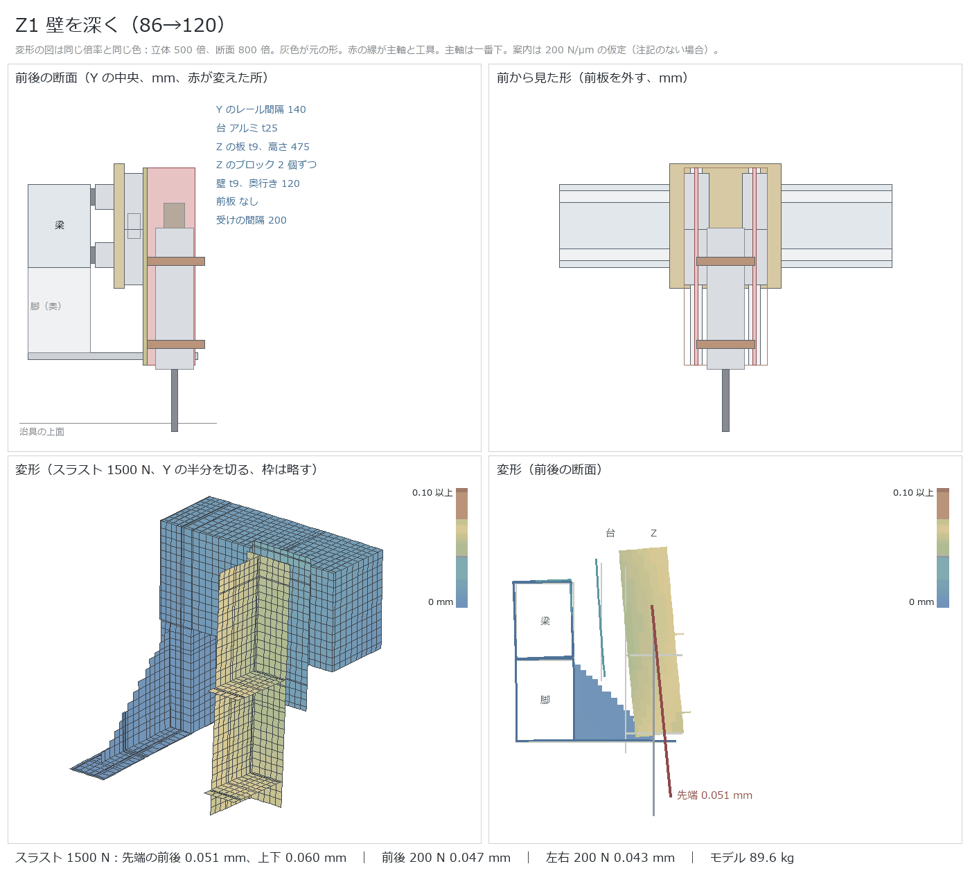
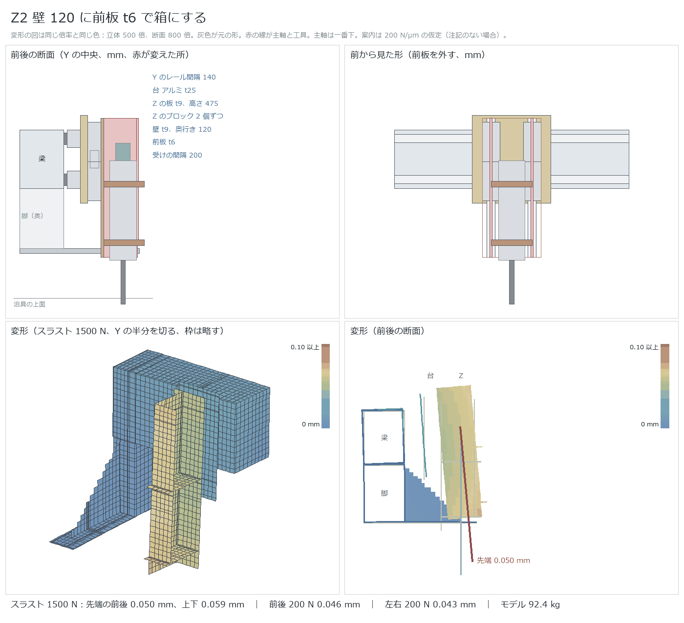
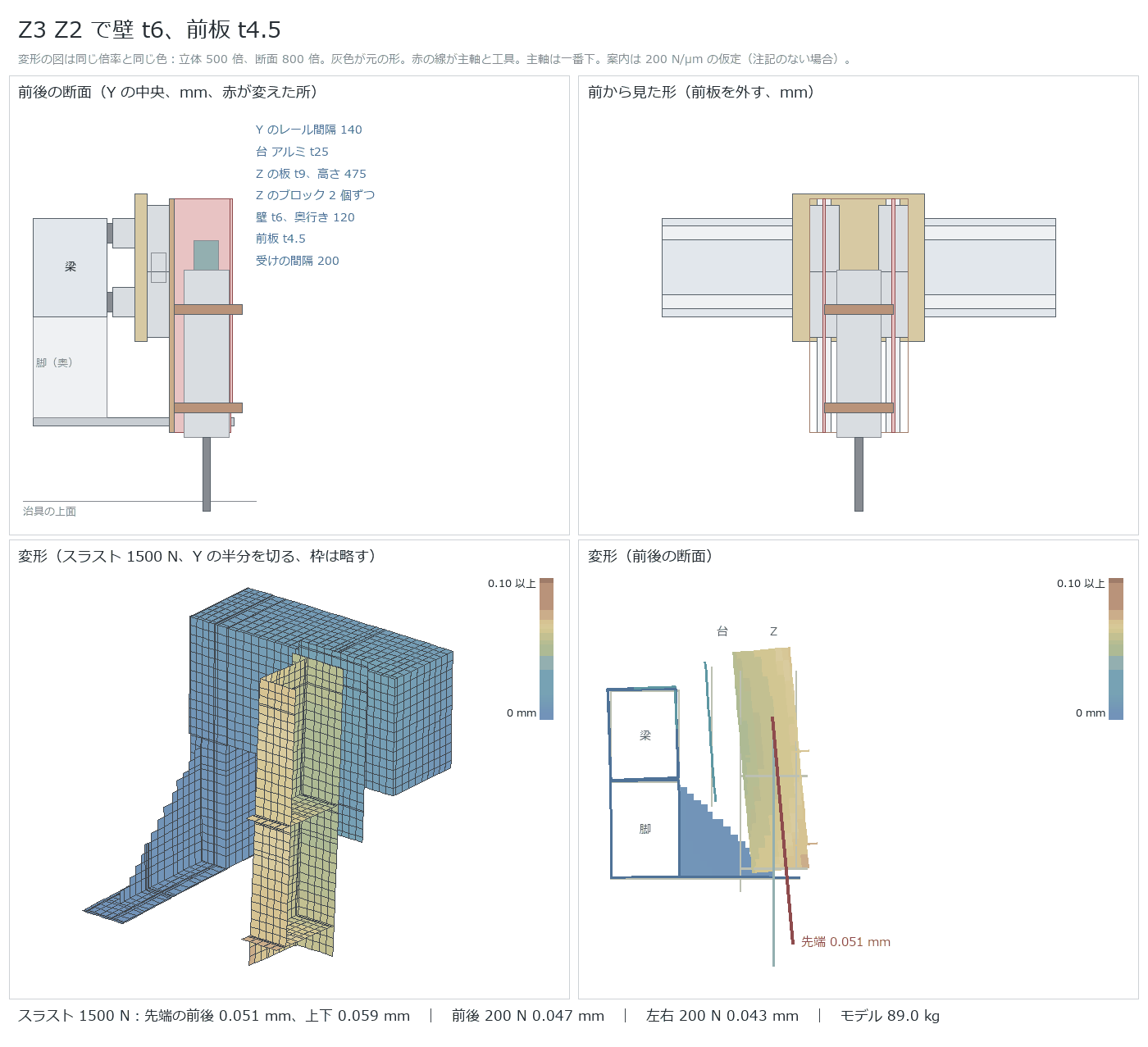
6.2 Plans for the Z section
Framework is common to Plan A.
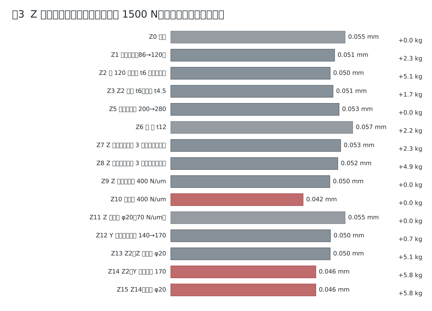
| Plan | Details | Tip, front-back | Tip, up-down | Front-back 200 N | Left-right 200 N | Model kg | Verdict |
|---|---|---|---|---|---|---|---|
| Z0 | Baseline | 0.055 | 0.060 | 0.050 | 0.043 | 87.3 | |
| Z1 | Wall depth 86 → 120 | 0.051 | 0.060 | 0.047 | 0.043 | 89.6 | Head goes inside the box |
| Z2 | Add t6 front plate to Z1 to make a box | 0.050 | 0.059 | 0.046 | 0.043 | 92.4 | |
| Z3 | Thin the plates in Z2. Walls t6, front plate t4.5 | 0.051 | 0.059 | 0.047 | 0.043 | 89.0 | 3.4 kg lighter for only a 0.001 mm difference. Adopted |
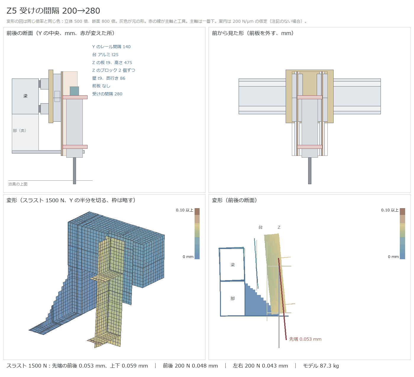
| Z5 | Head support spacing 200 → 280 | 0.053 | 0.059 | 0.048 | 0.043 | 87.3 | No weight change. Adopted |
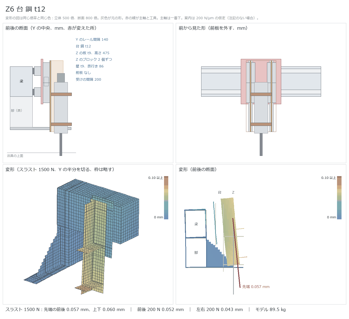
| Z6 | Make the base t12 steel | 0.057 | 0.060 | 0.052 | 0.043 | 89.5 | Actually worse |
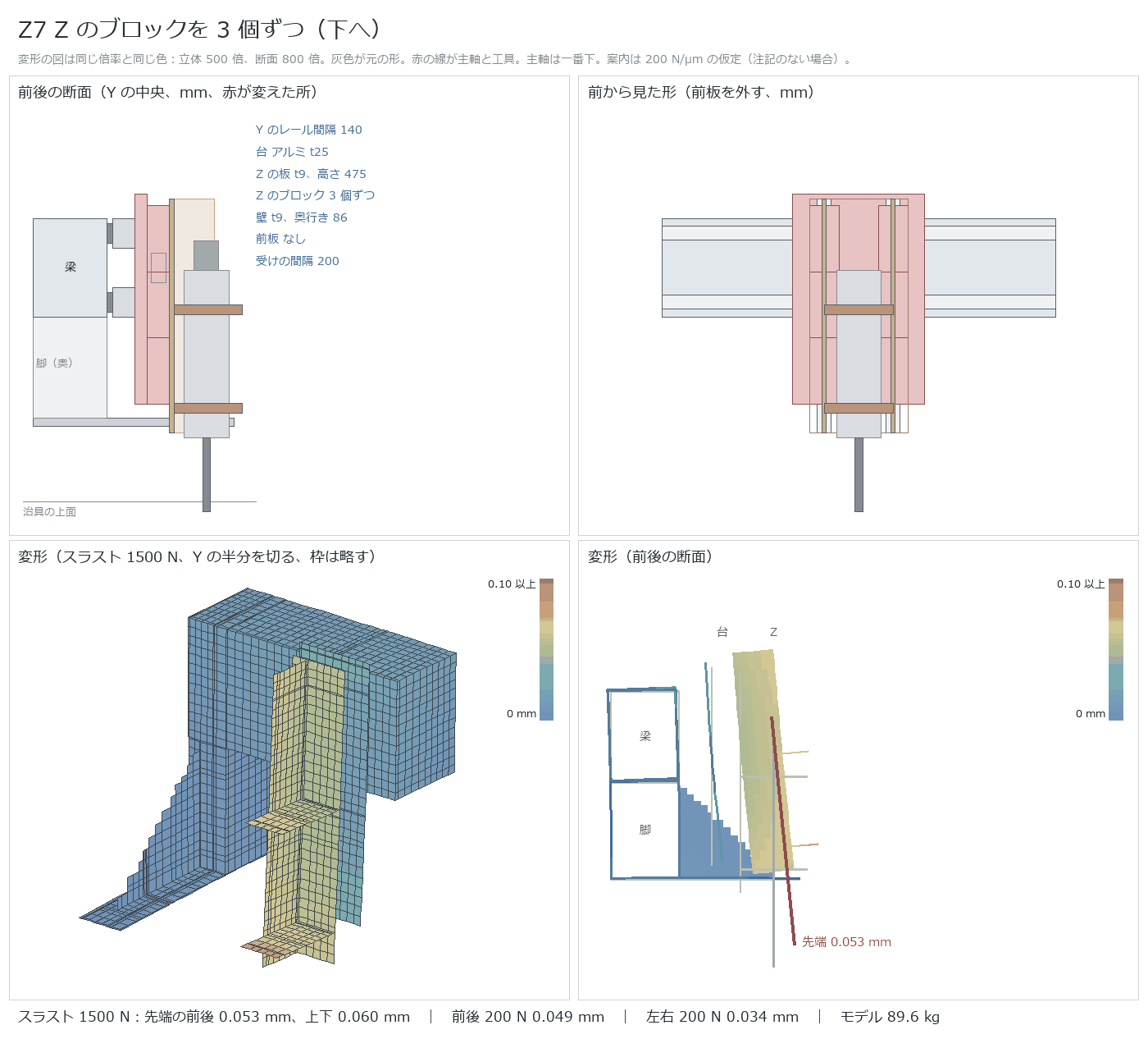
| Z7 | 3 Z blocks on each side (add below) | 0.053 | 0.060 | 0.049 | 0.034 | 89.6 | Effective against left-right lateral force. Risk of base hitting ribs |
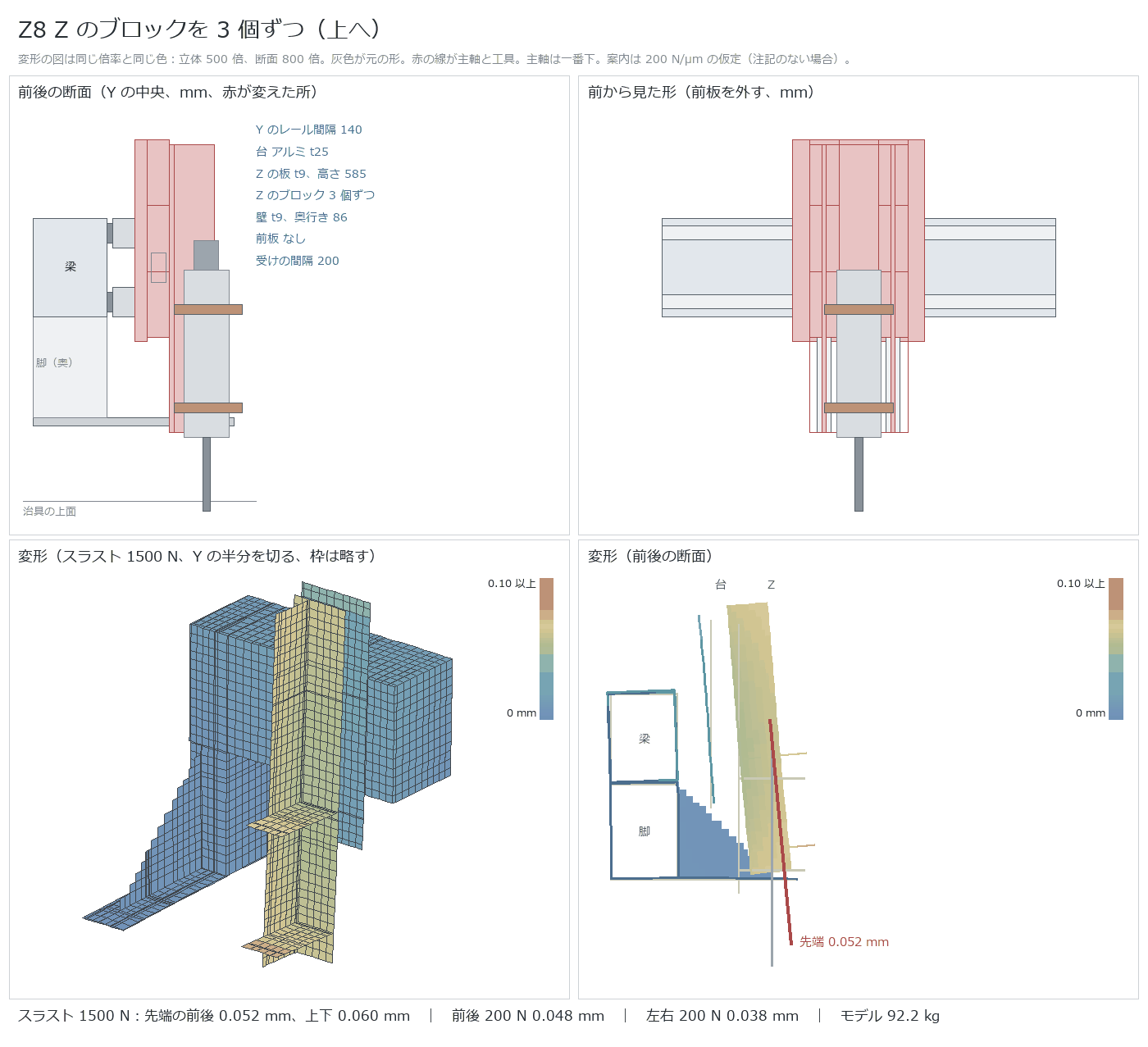
| Z8 | 3 Z blocks on each side (add above) | 0.052 | 0.060 | 0.048 | 0.038 | 92.2 | Z plate becomes 110 mm longer |
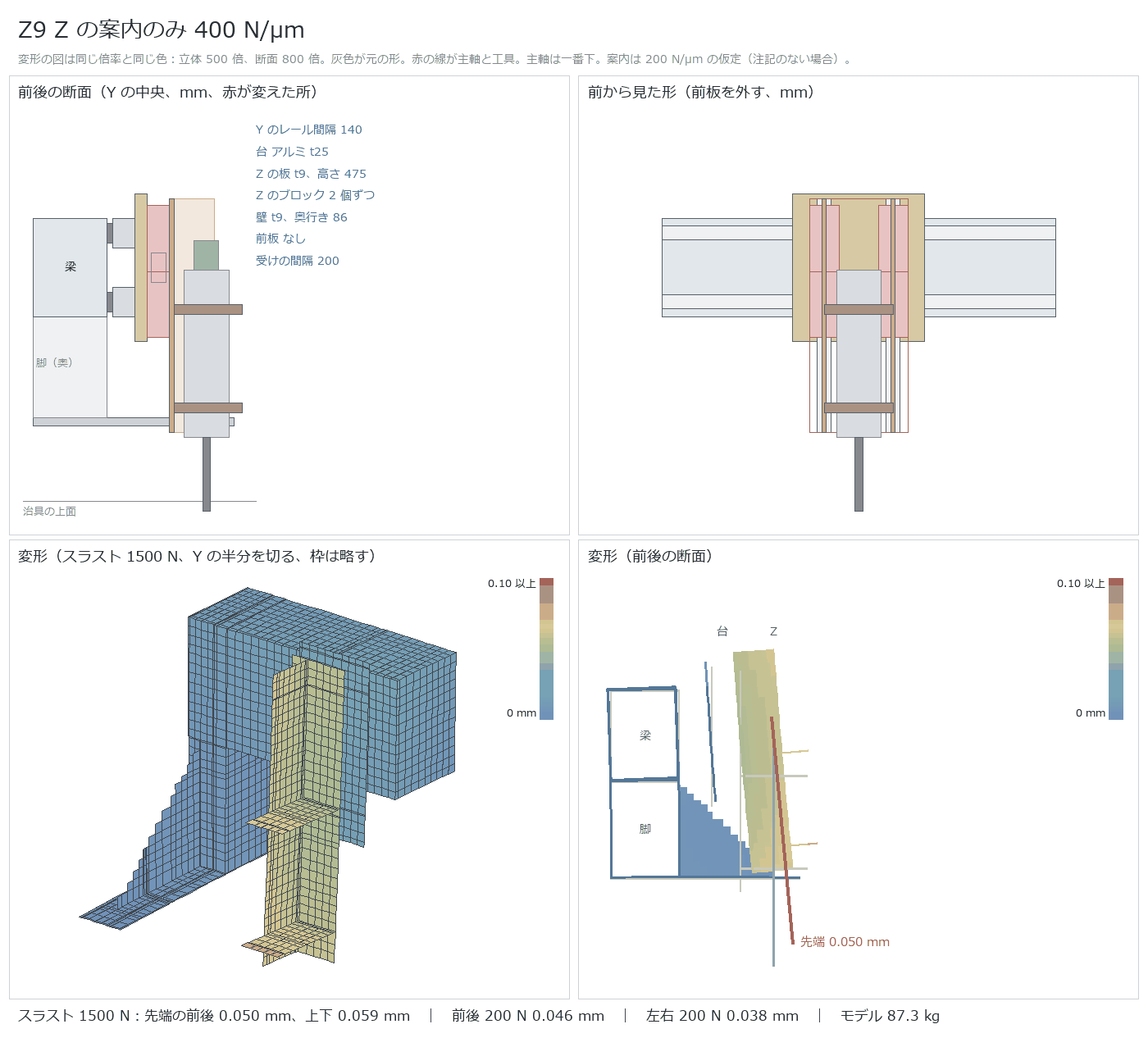
| Z9 | Z guide stiffness 400 N/µm | 0.050 | 0.059 | 0.046 | 0.038 | 87.3 | Same geometry. Checking the effect of stiffness |
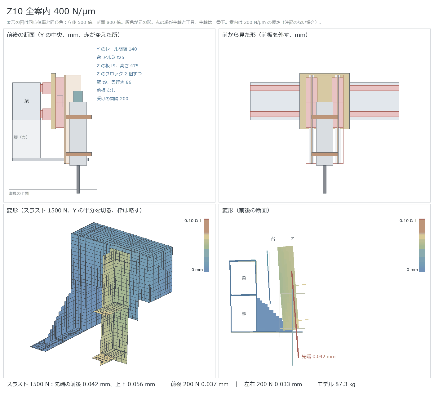
| Z10 | All guide stiffness 400 N/µm | 0.042 | 0.056 | 0.037 | 0.033 | 87.3 | Same geometry. Guides have the greatest effect |
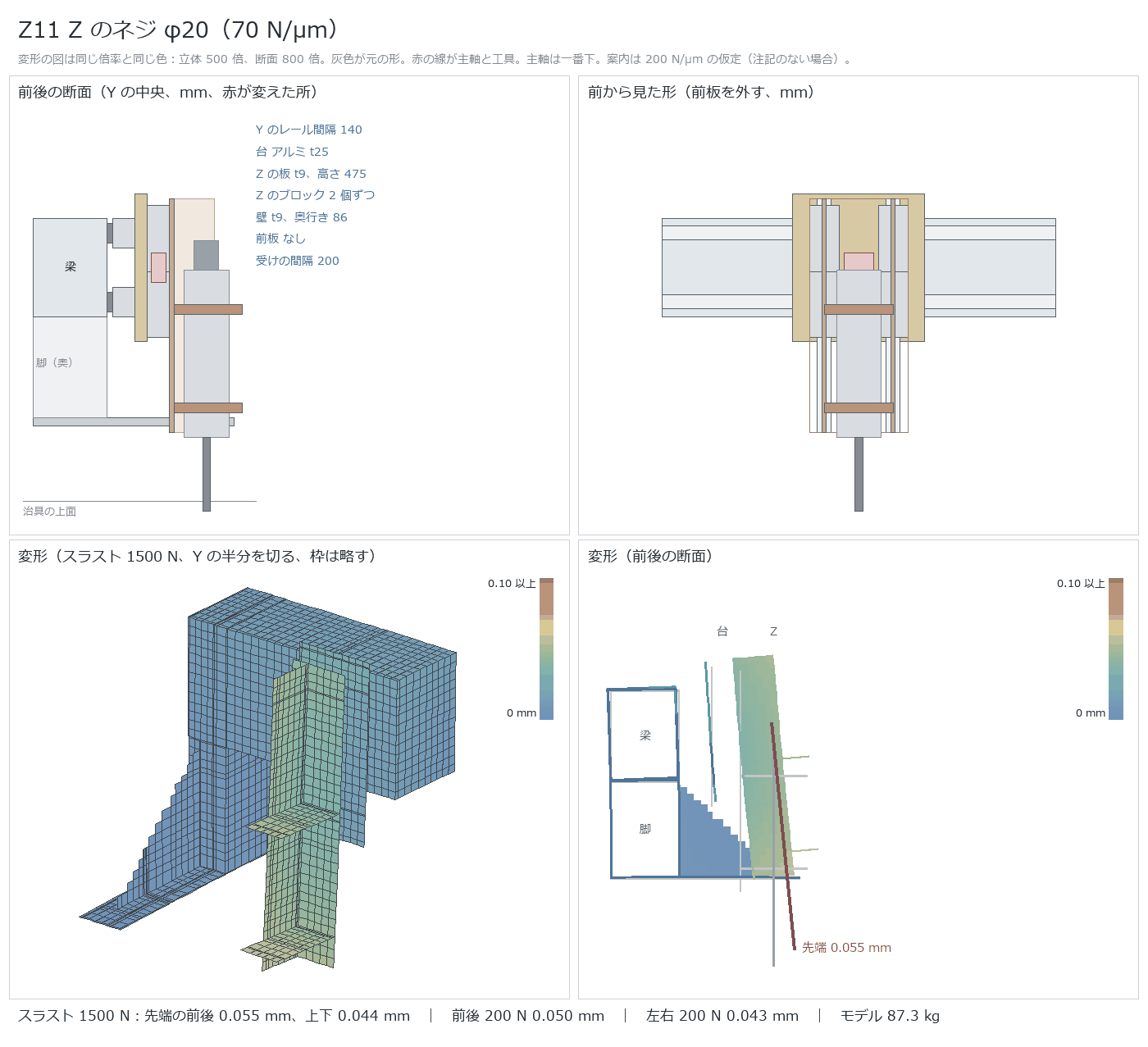
| Z11 | Z screw φ20 (70 N/µm) | 0.055 | 0.044 | 0.050 | 0.043 | 87.3 | Only up-down decreases |
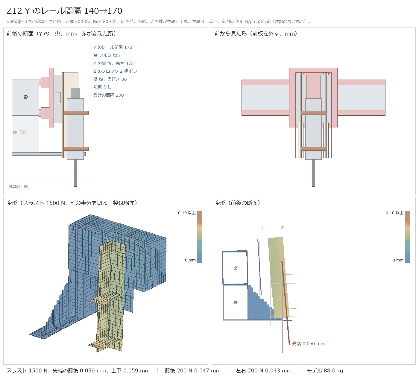
| Z12 | Y rail spacing 140 → 170 | 0.050 | 0.059 | 0.047 | 0.043 | 88.0 | Most efficient without adding weight. Adopted |
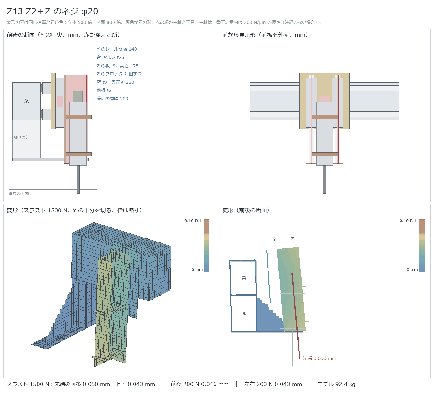
| Z13 | Z2 and Z11 | 0.050 | 0.043 | 0.046 | 0.043 | 92.4 | |
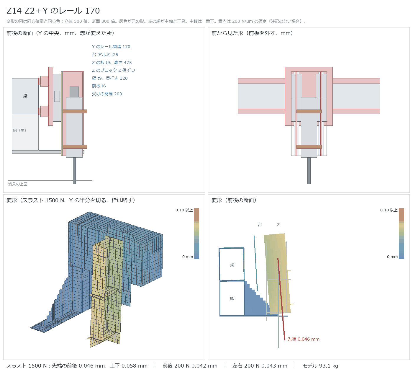
| Z14 | Z2 and Z12 | 0.046 | 0.058 | 0.042 | 0.043 | 93.1 | |
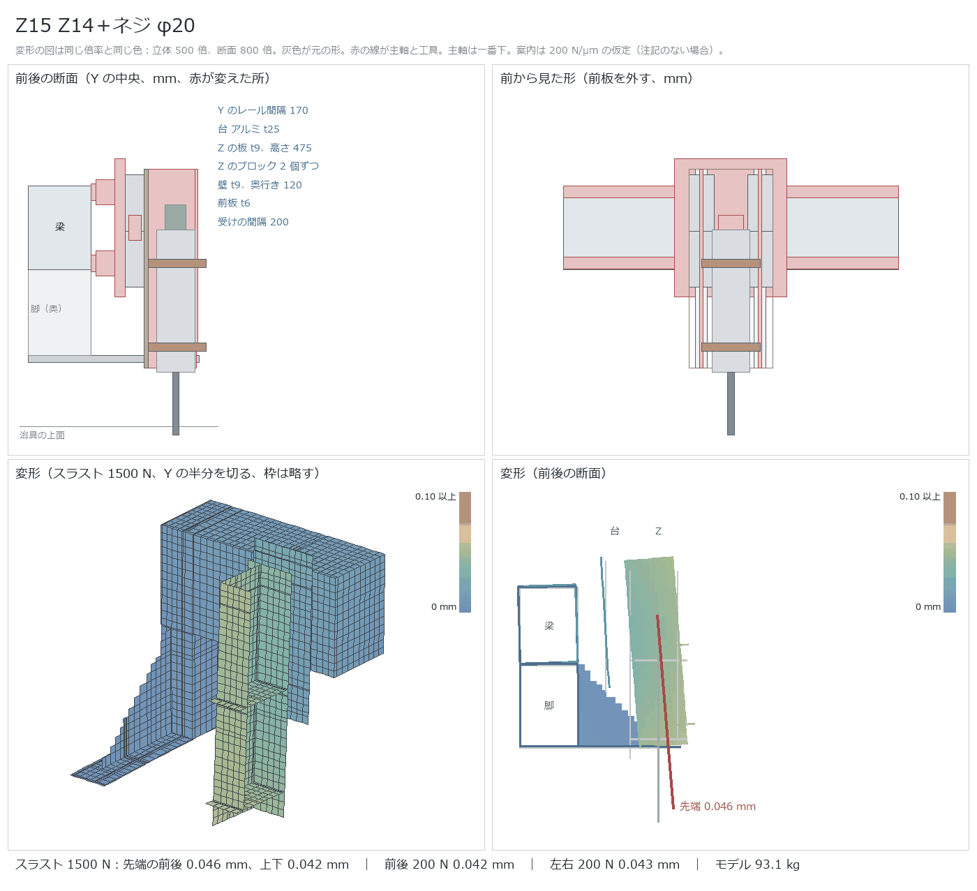
| Z15 | Z14 and Z11 | 0.046 | 0.042 | 0.042 | 0.043 | 93.1 |
The plan where the Z plate was made t6 (Z4) is not included in the results because the model nodes failed to connect and no solution was obtained.
Plan Z0: Baseline
Plan Z1: Wall depth 86 → 120
Plan Z2: Add t6 front plate to Z1 to make a box
Plan Z3: Thin the plates in Z2. Walls t6, front plate t4.5
Plan Z5: Head support spacing 200 → 280
Plan Z6: Make the base t12 steel
Plan Z7: 3 Z blocks on each side (add below)
Plan Z8: 3 Z blocks on each side (add above)
Plan Z9: Z guide stiffness 400 N/µm
Plan Z10: All guide stiffness 400 N/µm
Plan Z11: Z screw φ20 (70 N/µm)
Plan Z12: Y rail spacing 140 → 170
Plan Z13: Z2 and Z11
Plan Z14: Z2 and Z12
Plan Z15: Z14 and Z11
6.3 Combination Plans
| Plan | Details | Tip front-to-back | Tip up-and-down | Front-to-back 200 N | Left-to-right 200 N | Model kg |
|---|---|---|---|---|---|---|
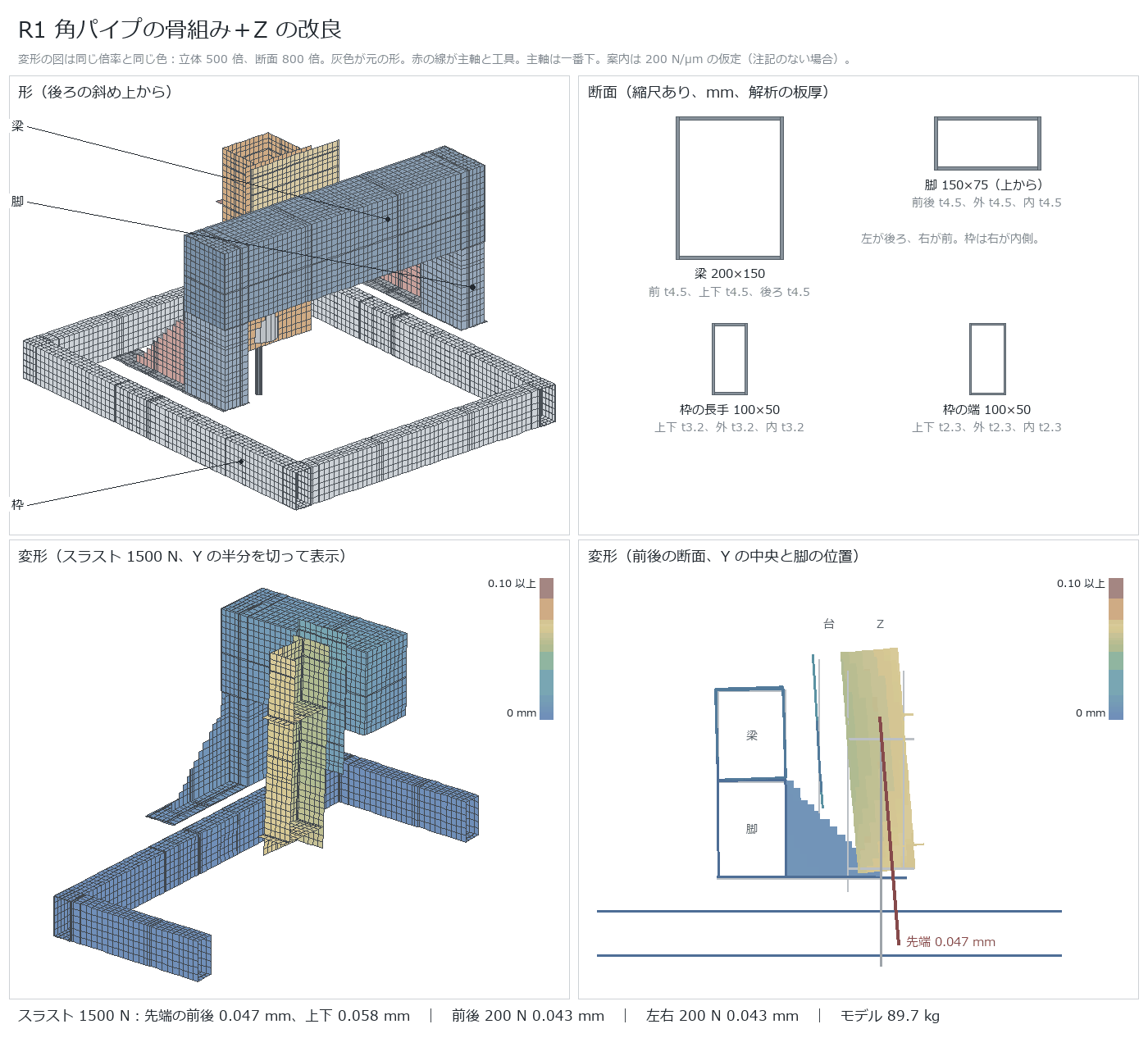
| R1 | Square pipe frame with Z improvements | 0.047 | 0.058 | 0.043 | 0.043 | 89.7 |
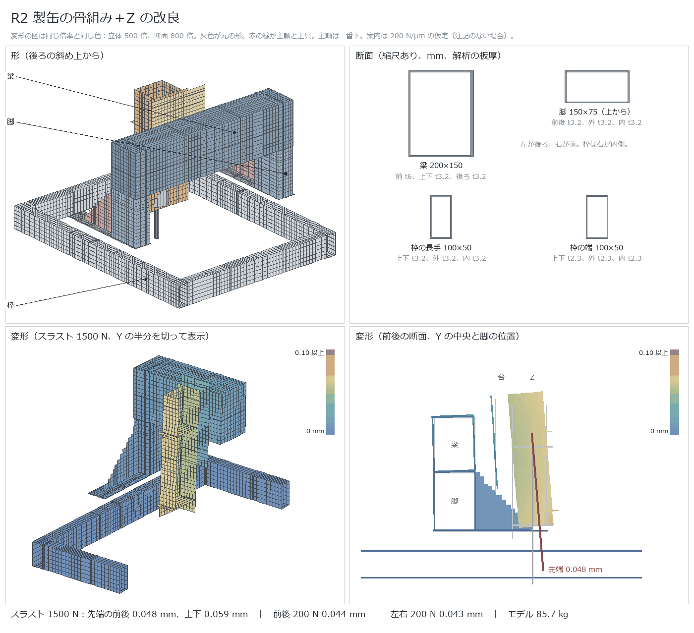
| R2 | Bent-plate frame with Z improvements | 0.048 | 0.059 | 0.044 | 0.043 | 85.7 |
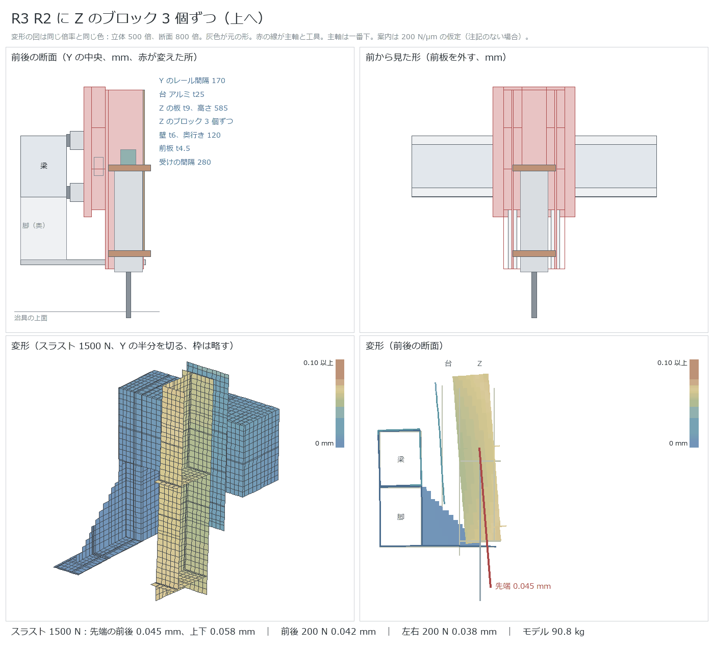
| R3 | R2 with 3 Z blocks each | 0.045 | 0.058 | 0.042 | 0.038 | 90.8 |
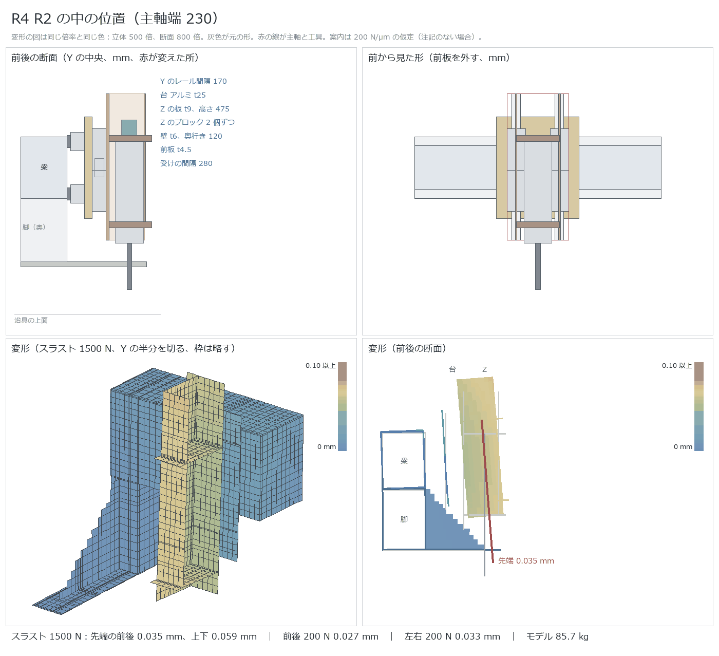
| R4 | R2 with spindle nose at 230 | 0.035 | 0.059 | 0.027 | 0.033 | 85.7 |
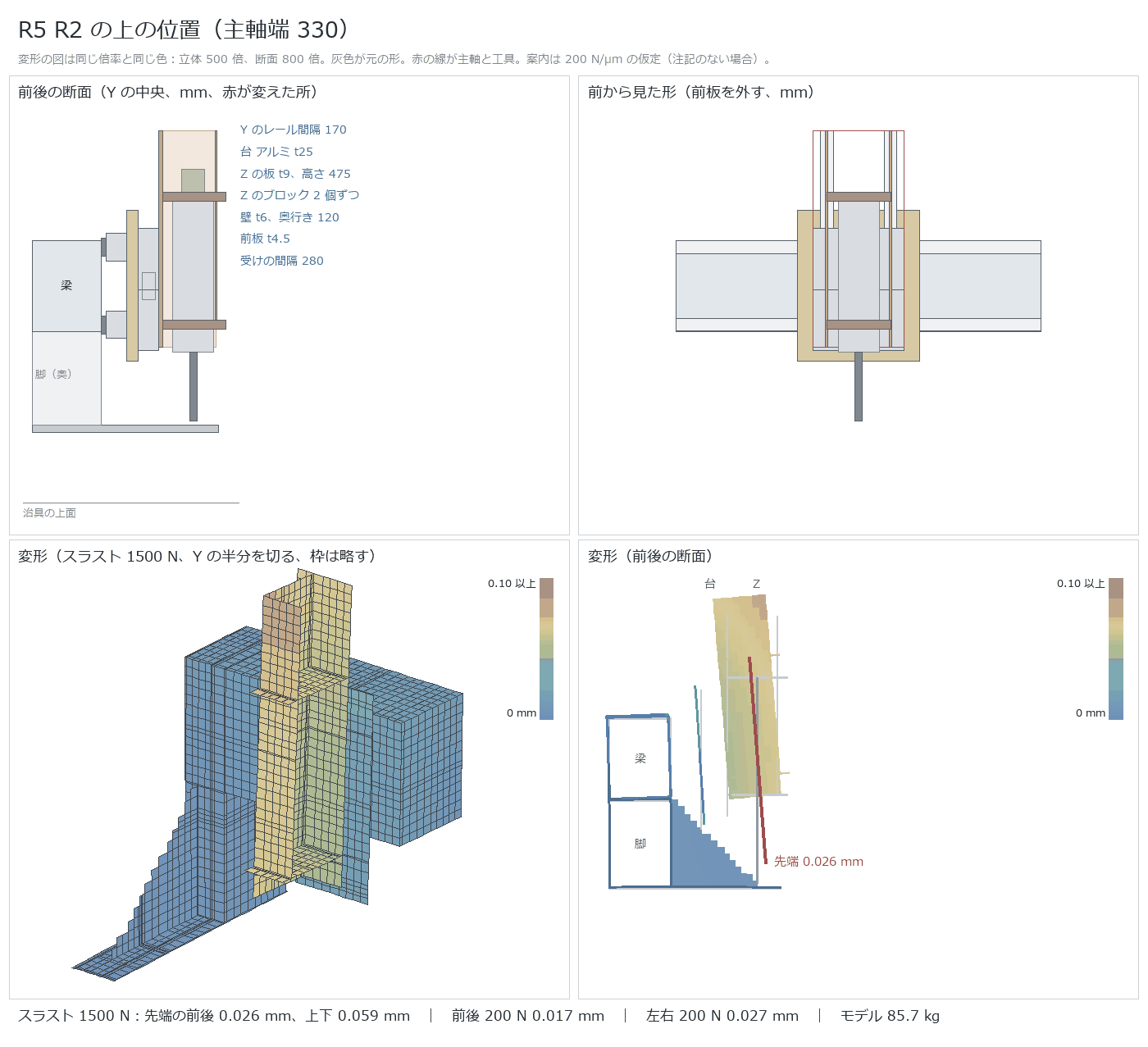
| R5 | R2 with spindle nose at 330 | 0.026 | 0.059 | 0.017 | 0.027 | 85.7 |
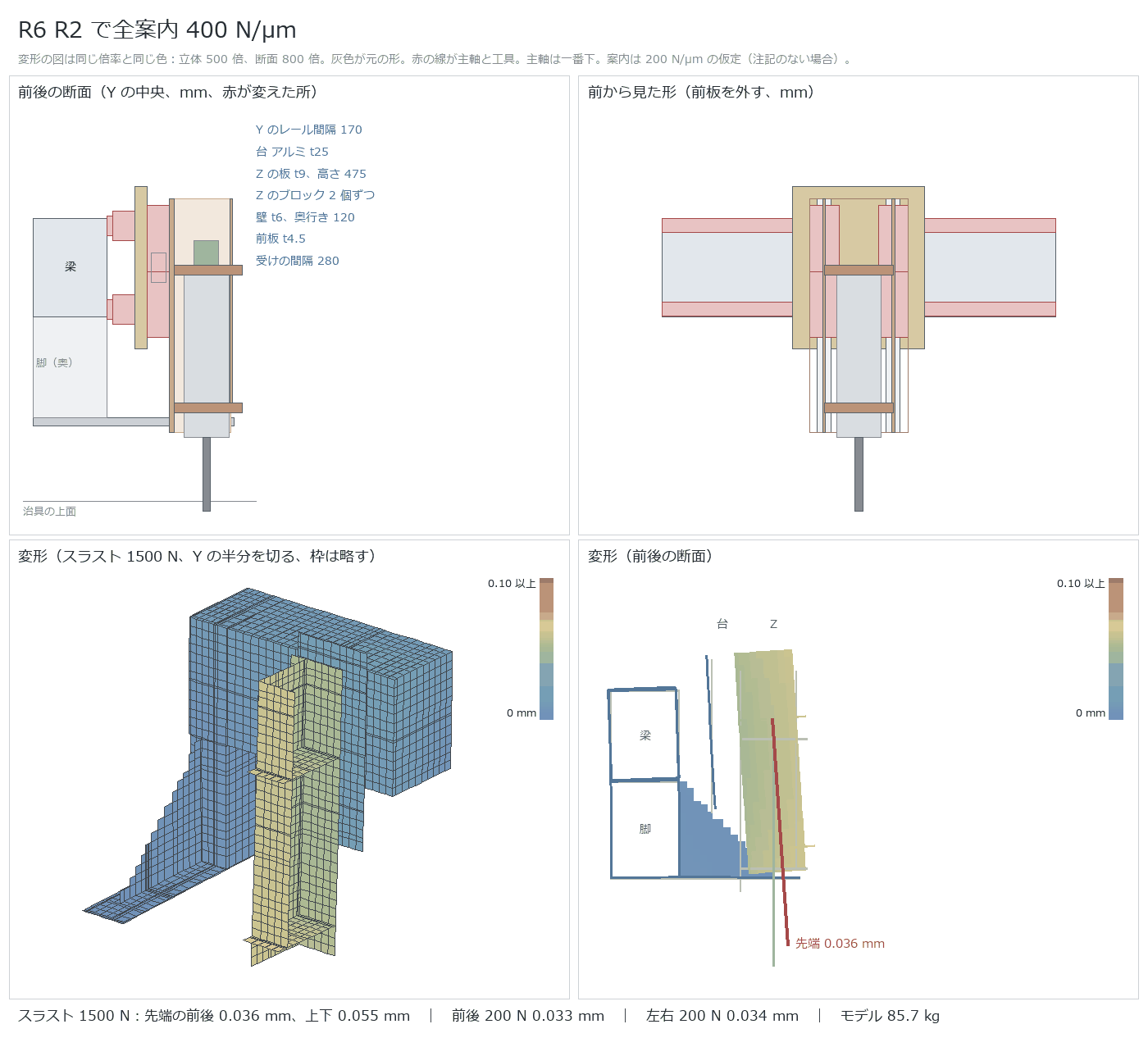
| R6 | R2 with 400 N/µm guides | 0.036 | 0.055 | 0.033 | 0.034 | 85.7 |
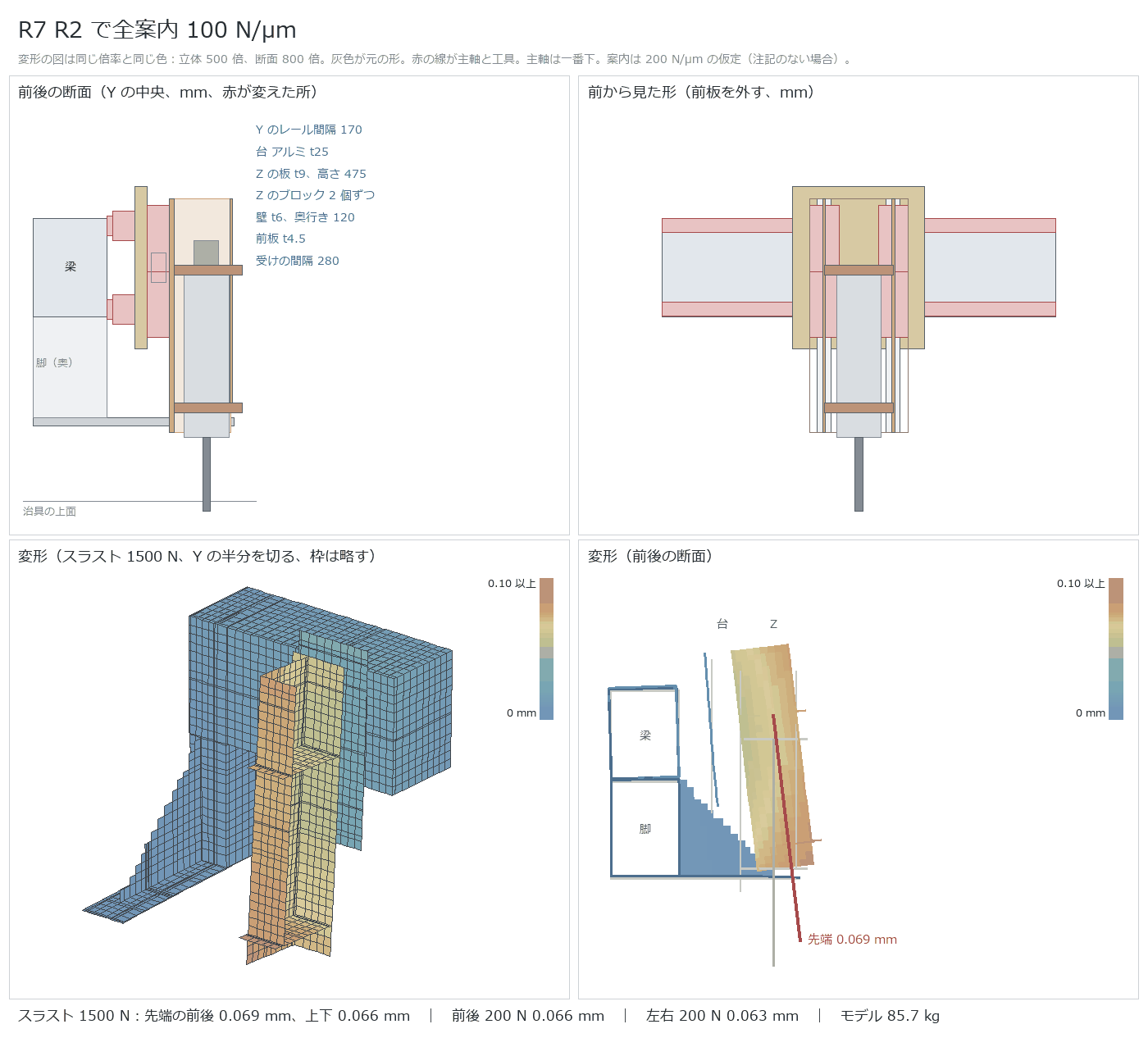
| R7 | R2 with 100 N/µm guides | 0.069 | 0.066 | 0.066 | 0.063 | 85.7 |
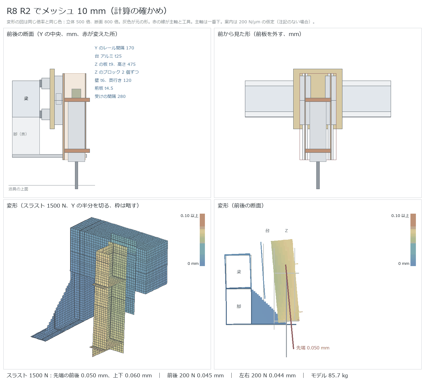
| R8 | R2 with 10 mm mesh | 0.050 | 0.060 | 0.045 | 0.044 | 85.7 |
R8 was to check the mesh; the difference between 15 mm and 10 mm is about 4%. Seeing that raising the spindle reduced front-to-back deflection led directly to the next plan.
Plan R1: Square pipe frame with Z improvements
Plan R2: Bent-plate frame with Z improvements
Plan R3: R2 with 3 Z blocks each
Plan R4: R2 with spindle nose at 230
Plan R5: R2 with spindle nose at 330
Plan R6: R2 with 400 N/µm guides
Plan R7: R2 with 100 N/µm guides
Plan R8: R2 with 10 mm mesh
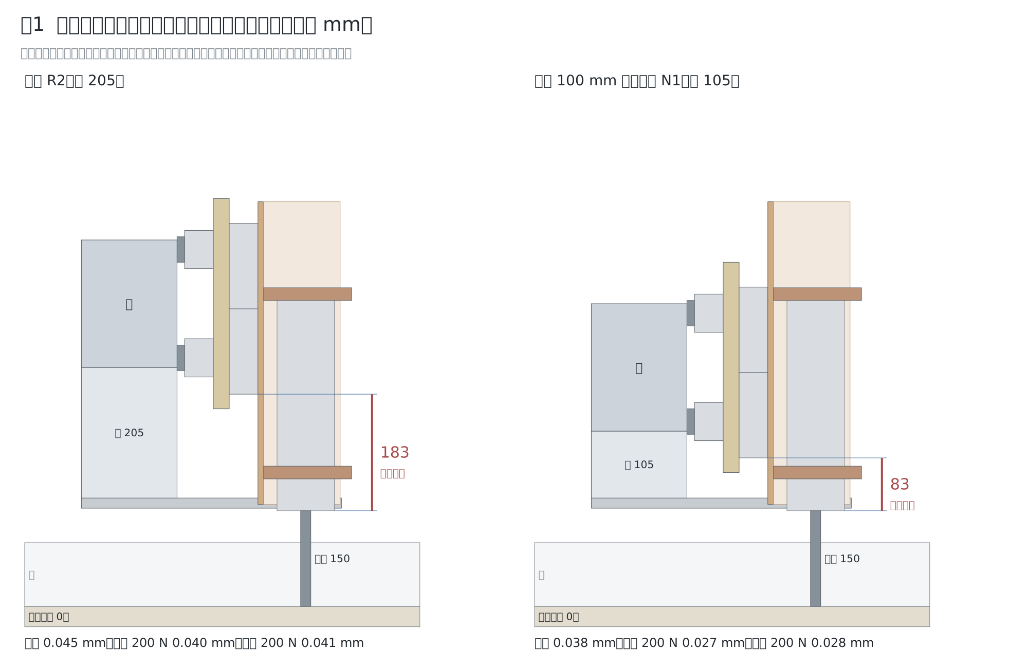
6.4 Shortening the legs to run the spindle close to the beam
For the same machining plane height, shortening the legs lets the spindle machine closer to the Z blocks. This works well because we mostly machine plates and only need a small distance between the beam and the workpiece.
| Plane height | Legs | Tip front-to-back | Tip up-and-down | Front-to-back 200 N | Left-to-right 200 N |
|---|---|---|---|---|---|
| 0 | 205 | 0.045 | 0.059 | 0.040 | 0.041 |
| 0 | 155 | 0.041 | 0.059 | 0.033 | 0.034 |
| 0 | 105 (adopted) | 0.038 | 0.061 | 0.027 | 0.028 |
| 0 | 75 | 0.041 | 0.063 | 0.026 | 0.025 |
| 50 | 205 | 0.040 | 0.059 | 0.032 | 0.036 |
| 50 | 155 | 0.034 | 0.059 | 0.025 | 0.029 |
| 50 | 105 (adopted) | 0.033 | 0.061 | 0.021 | 0.025 |
| 50 | 75 | 0.033 | 0.063 | 0.019 | 0.023 |
| 100 | 205 | 0.033 | 0.059 | 0.024 | 0.031 |
| 100 | 155 | 0.029 | 0.059 | 0.020 | 0.026 |
- With 75 mm legs, the ribs become shorter, making thrust deflection worse than with 105 mm legs. We decided to go with 105 mm legs.
- Increasing rib thickness from t9 to t16 adds 1.2 kg and shifts deflection from 0.038 → 0.036 mm (plane height 0). Not essential.
- Stroke has no effect on deflection when operating at the same position.
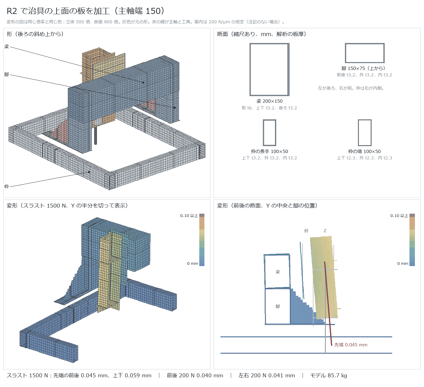
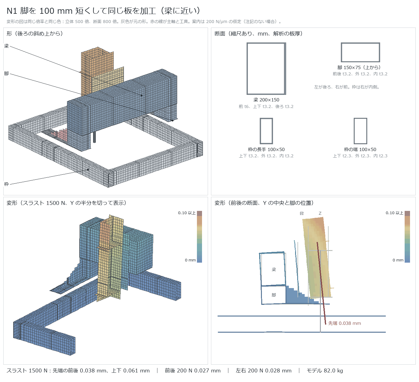
6.5 Base height and plate ribs
| Conditions (W 40–52, L 125) | Tip front-to-back | Plate deflection | Left-to-right 200 N |
|---|---|---|---|
| Base height 100, 7 ribs, plate t16 | 0.034 | 0.017 | 0.026 |
| Base height 75 | 0.034 | 0.038 | 0.026 |
| Base height 50 (adopted) | 0.034 | 0.075 | 0.026 |
| Base height 100, plate t12 | 0.032 | 0.027 | 0.025 |
| Base height 100, 3 ribs | 0.032 | 0.021 | 0.025 |
| Base height 100, no ribs | 0.032 | 0.124 | 0.025 |
Front-to-back and left-to-right deflections do not change with base height. What changes is only the plate deflection (up-and-down), which affects blind hole depth.
6.6 Z front plate
| Plane height | Front plate | Tip front-to-back | Tip up-and-down | Front-to-back 200 N | Left-to-right 200 N | Model kg |
|---|---|---|---|---|---|---|
| 0 | t4.5 | 0.038 | 0.061 | 0.027 | 0.028 | 82.0 |
| 0 | None | 0.038 | 0.061 | 0.027 | 0.028 | 79.9 |
| 50 | t4.5 | 0.033 | 0.061 | 0.021 | 0.025 | 82.0 |
| 50 | None | 0.033 | 0.061 | 0.021 | 0.025 | 79.9 |
Because there is hardly any difference at working positions, we decided not to treat the front plate as a structural member, but rather as a cover. This assumes that the fastening between the head and the bracket is solid.
6.7 Base material
We do not machine aluminum because the chips would get mixed in. We checked whether using steel for the base would also work. Plane height 0, tool 150. A thinner base also brings the spindle closer to the beam.
| Bed | Tip front-back | Tip up-down | Front-back 200 N | Left-right 200 N | Bed kg | Model kg | Lowest natural frequency |
|---|---|---|---|---|---|---|---|
| Aluminum t25 (current) | 0.038 | 0.061 | 0.027 | 0.028 | 6.0 | 78.6 | 72 Hz |
| Steel t25 | 0.037 | 0.061 | 0.026 | 0.027 | 17.4 | 90.0 | 67 Hz |
| Steel t20 | 0.038 | 0.061 | 0.026 | 0.027 | 13.9 | 86.5 | 69 Hz |
| Steel t16 | 0.038 | 0.061 | 0.027 | 0.028 | 11.1 | 83.7 | 69 Hz |
| Steel t12 | 0.040 | 0.061 | 0.028 | 0.028 | 8.3 | 80.9 | 71 Hz |
| Steel t9 | 0.042 | 0.062 | 0.029 | 0.028 | 6.2 | 78.8 | 71 Hz |
| Steel t12 + cross plate t6 | 0.039 | 0.061 | 0.027 | 0.028 | 9.6 | 82.2 | 70 Hz |
| Steel t9 + cross plate t6 | 0.040 | 0.062 | 0.028 | 0.028 | 7.5 | 80.1 | 71 Hz |
| Steel t16 + cross plate t6 | 0.038 | 0.061 | 0.027 | 0.028 | 12.4 | 85.0 | 69 Hz |
We decided to use steel t12. Compared to aluminum t25, the tip displacement is only 0.0015 mm larger, it is only 2.3 kg heavier, and there are no vibration issues. The earlier sections (6.1 to 6.6) compared options solved with an aluminum bed, but the relative ranking among the options does not change.
6.8 Lightening the framework (lightening cutouts and plate thicknesses)
We checked whether we could reduce weight while maintaining strength using lightening holes. Calculations were done using the current design (steel t12 bed, surface height 0, tool 150).
Conclusions
- Lightening holes are not worth it. Even if we drill out all the plates where holes can be made (bulkheads, Z-wall, ribs), it only saves 1.7 kg (less than 1% of the machine), while increasing tool tip displacement by up to 10.3%.
- Redistributing plate thicknesses is better. If we drop plates that don't do much by one thickness step and slightly thicken effective areas (front of the legs, ribs), we save 6.2 kg, and displacement actually decreases (see "Light 6" below).
- There is plenty of safety margin for strength (not breaking). The maximum stress is 22 MPa, which is less than 1/10 of the yield point of steel (SS400), 245 MPa. What determines plate thickness is deflection, not strength.
Weight breakdown and effective parts
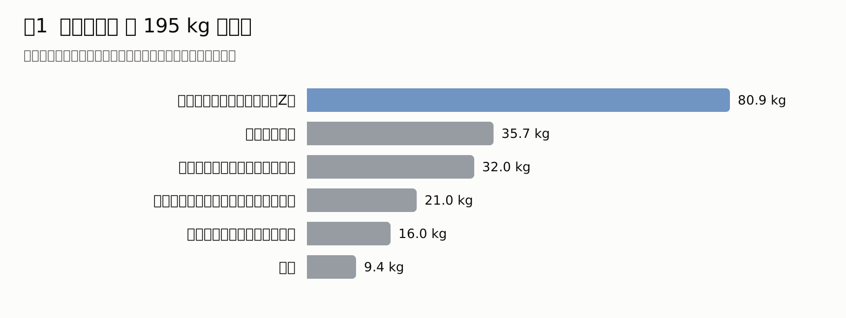
The framework weighs 80.9 kg, and the rest consists of purchased items like linear guides, the head, motors, and wiring. Only the framework can be changed via cutouts or plate thicknesses.
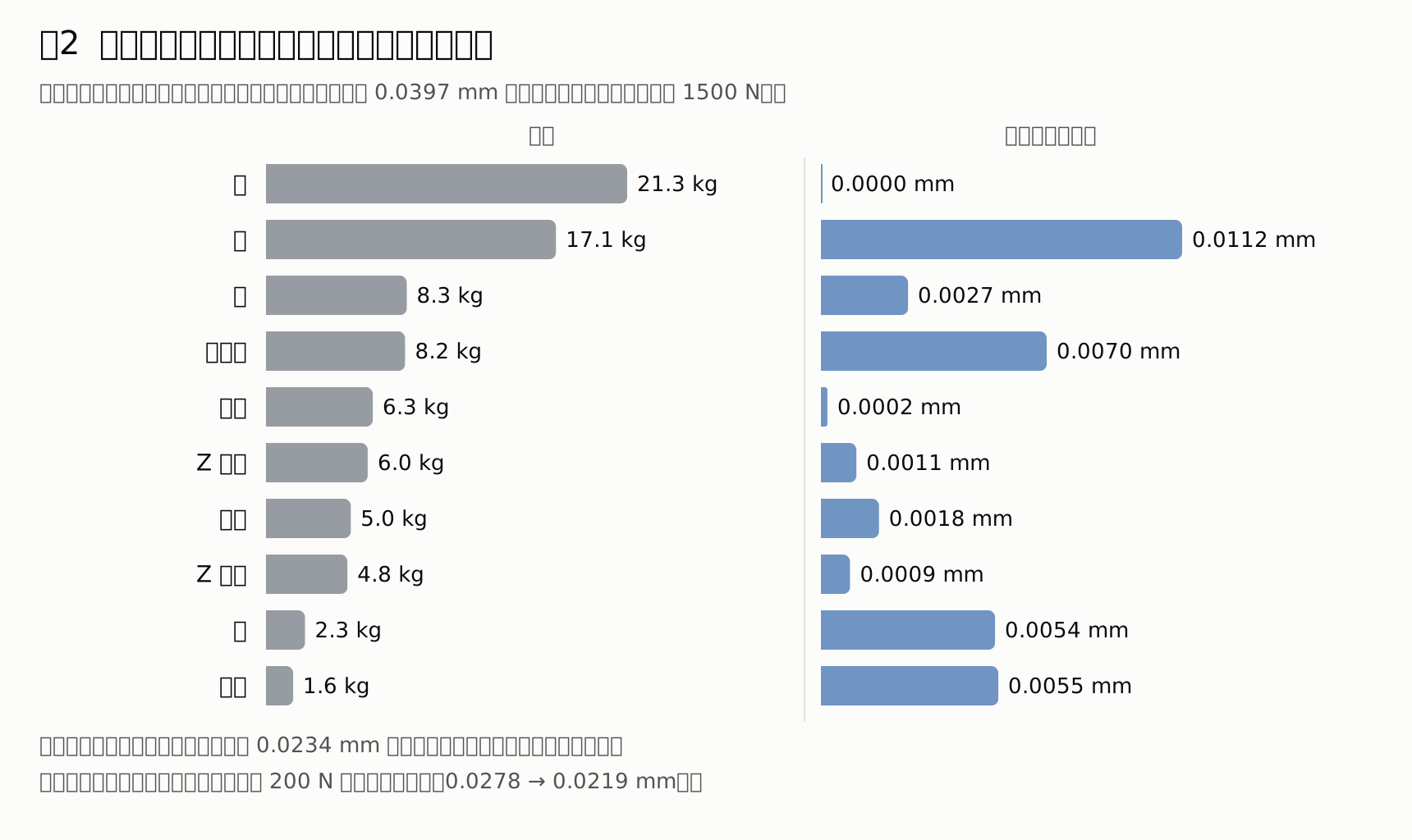
- What matters most are the guides (linear guides). They are also heavy at 35.7 kg, but if their rigidity drops, displacement increases significantly (0.056 mm in the 6.11 example with 100 N/µm rigidity), so we won't downsize them.
- Within the framework, the beam, foot plates, legs, and ribs are effective. Although the legs and ribs together are light at 3.9 kg, they have a far greater effect than the 6.3 kg bracket.
- The bracket, Z-wall, bulkheads, and frame ends do very little for their weight. These are candidates for weight reduction.
Lightening holes
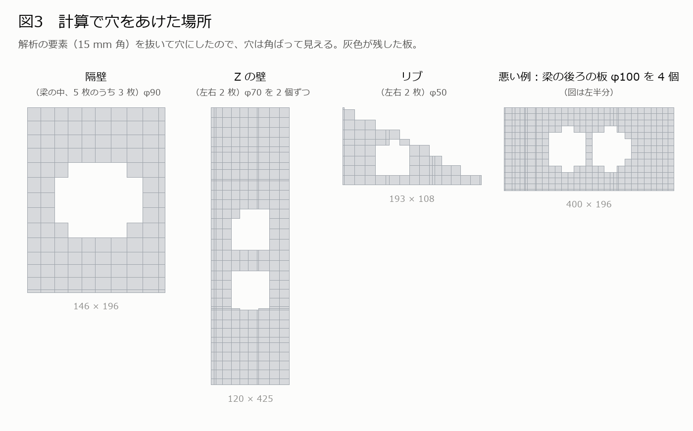
| Option | Weight saved kg | Tip front-back | Tip up-down | Front-back 200 N | Left-right 200 N | Lowest natural frequency |
|---|---|---|---|---|---|---|
| No holes (current) | 0.0 | 0.0397 (+0.0%) | 0.0614 (+0.0%) | 0.0279 (+0.0%) | 0.0278 (+0.0%) | 71 Hz |
| φ90 in bulkheads (3 plates) | 0.7 | 0.0409 (+3.0%) | 0.0616 (+0.3%) | 0.0294 (+5.4%) | 0.0279 (+0.4%) | 71 Hz |
| φ70 x 2 in Z-walls (2 plates) | 0.7 | 0.0404 (+1.8%) | 0.0616 (+0.3%) | 0.0283 (+1.4%) | 0.0278 (+0.0%) | 71 Hz |
| φ50 in ribs (2 plates) | 0.3 | 0.0419 (+5.5%) | 0.0625 (+1.8%) | 0.0285 (+2.2%) | 0.0279 (+0.4%) | 71 Hz |
| All 3 locations | 1.7 | 0.0438 (+10.3%) | 0.0630 (+2.6%) | 0.0304 (+9.0%) | 0.0279 (+0.4%) | 71 Hz |
| φ100 x 4 in rear beam plate (bad example) | 0.7 | 0.0401 (+1.0%) | 0.0614 (+0.0%) | 0.0303 (+8.6%) | 0.0279 (+0.4%) | 71 Hz |
- Since holes hollow out the middle of a plate, thinning the plate produces less displacement for the same weight reduction. In the bulkheads, saving 0.7 kg with holes increases front-back 200 N displacement by +5.4%, but going from t4.5 to 3.2 saves 1.4 kg with only a +1.1% increase.
- The ribs are small triangles, so holes end up right in the middle of the load path. Even a φ50 hole increases tip front-back displacement by +5.5%.
- Drilling holes in the rear plate of the beam opens up the closed box, weakening it against torsion (+8.6% under front-back 200 N). We will not make holes in the face of the box.
- We will make holes only when there is a specific need, such as routing wiring or piping, venting air during welding, or reaching in to tighten bolts.
- Refining the mesh elements from 15 mm to 7.5 mm showed the same trend (tip front-back: no holes 0.0421, bulkhead holes 0.0432 (+2.6%), rib holes 0.0451 (+7.1%)).
Changing plate thickness by one step
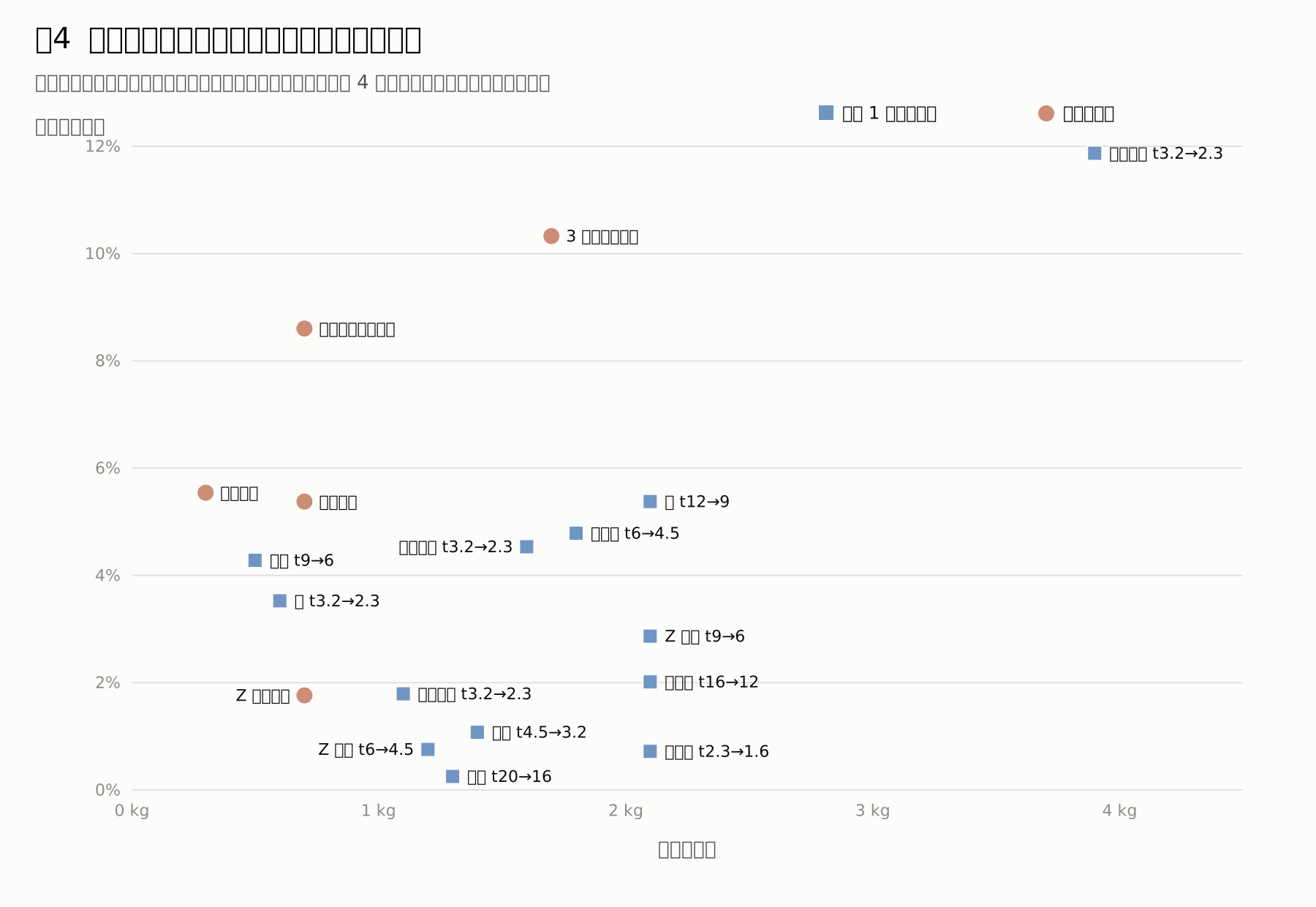
| Thinned part | Weight saved kg | Largest displacement increase | Notes |
|---|---|---|---|
| Bracket t20→16 | 1.3 | +0.3% | Shortens the clamping length on the spindle. We will verify this when deciding how to mount the head |
| Frame ends t2.3→1.6 | 2.1 | +0.7% | The end frames only support the X-axis screw BF12 |
| Z-wall t6→4.5 | 1.2 | +0.8% | Assumes attachment by welding |
| Bulkhead t4.5→3.2 | 1.4 | +1.1% | |
| Beam rear t3.2→2.3 | 1.1 | +1.8% | |
| Z-plate t9→6 | 2.1 | +2.9% | Do not use. Thread depth for mounting the Z-axis rails is insufficient |
| Foot plate t16→12 | 2.1 | +2.0% | |
| Frame length t3.2→2.3 | 3.9 | +11.9% | Do not use. Left-right displacement and frequency get worse |
| Beam top/bottom t3.2→2.3 | 1.6 | +4.5% | |
| Beam front t6→4.5 | 1.8 | +4.8% | |
| Bed t12→9 | 2.1 | +5.4% | |
| Ribs t9→6 | 0.5 | +4.3% | |
| Legs t3.2→2.3 | 0.6 | +3.5% |
| Thicken | Added weight kg | Tip fore-aft | Effect per 1 kg |
|---|---|---|---|
| Leg front only t3.2→6 | 0.4 | 0.0388 (−2.3%) | 5.7% |
| Rib t9→12 | 0.5 | 0.0388 (−2.3%) | 4.5% |
| Leg t3.2→4.5 | 1.0 | 0.0385 (−3.0%) | 3.0% |
| Foot plate t16→19 | 1.5 | 0.0392 (−1.3%) | 0.8% |
| Beam top & bottom t3.2→4.5 | 2.4 | 0.0382 (−3.8%) | 1.6% |
| Base t12→16 | 2.8 | 0.0384 (−3.3%) | 1.2% |
| Beam front t6→9 | 3.7 | 0.0376 (−5.3%) | 1.4% |
| Foot plate t16→22 | 3.1 | 0.0387 (−2.5%) | 0.8% |
| Frame long sides t3.2→4.5 | 5.8 | 0.0397 (+0.0%) | 0.0% |
"Worst displacement increase" is the largest increase among four cases: tip fore-aft, tip vertical, 200 N fore-aft, and 200 N left-right. For thickening, the front of the legs and the ribs are the most effective per 1 kg. Thickening the beam or foot plates works, but adds quite a bit of weight.
Weight-reduction options
| Option | Weight saved kg | Tip fore-aft | Tip vertical | Fore-aft 200 N | Left-right 200 N | Lowest natural frequency |
|---|---|---|---|---|---|---|
| Current | 0.0 | 0.0397 (+0.0%) | 0.0614 (+0.0%) | 0.0279 (+0.0%) | 0.0278 (+0.0%) | 71 Hz |
| Light 1: Frame ends 1.6, bulkheads 3.2, Z walls 4.5 | 4.7 | 0.0404 (+1.8%) | 0.0616 (+0.3%) | 0.0284 (+1.8%) | 0.0281 (+1.1%) | 71 Hz |
| Light 2: Light 1 + mounts 16 | 6.0 | 0.0404 (+1.8%) | 0.0617 (+0.5%) | 0.0285 (+2.2%) | 0.0281 (+1.1%) | 71 Hz |
| Light 3: Light 1 + leg front 6, rib 12 | 3.8 | 0.0386 (−2.8%) | 0.0606 (−1.3%) | 0.0280 (+0.4%) | 0.0278 (+0.0%) | 71 Hz |
| Light 4: Light 2 + leg front 6, rib 12 | 5.1 | 0.0387 (−2.5%) | 0.0606 (−1.3%) | 0.0280 (+0.4%) | 0.0278 (+0.0%) | 72 Hz |
| Light 5: Light 4 + beam back 2.3 | 6.2 | 0.0390 (−1.8%) | 0.0608 (−1.0%) | 0.0285 (+2.2%) | 0.0279 (+0.4%) | 72 Hz |
| Light 4, leg front 9 | 4.8 | 0.0381 (−4.0%) | 0.0602 (−2.0%) | 0.0279 (+0.0%) | 0.0277 (−0.4%) | 72 Hz |
| Light 4, rib 16 | 4.4 | 0.0380 (−4.3%) | 0.0603 (−1.8%) | 0.0278 (−0.4%) | 0.0278 (+0.0%) | 72 Hz |
| Light 4, foot plate 12 | 7.2 | 0.0393 (−1.0%) | 0.0609 (−0.8%) | 0.0283 (+1.4%) | 0.0279 (+0.4%) | 72 Hz |
| Light 6: Light 4 + foot plate 12, leg front 9, rib 16 | 6.2 | 0.0380 (−4.3%) | 0.0602 (−2.0%) | 0.0280 (+0.4%) | 0.0277 (−0.4%) | 72 Hz |
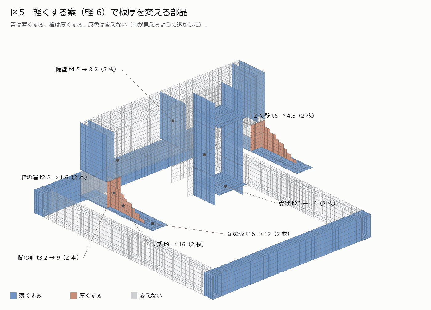
If you reduce weight purely by plate thickness, we recommend Light 6. If you can extend the ribs to the front face of the beam, Light 7 in Section 6.10 is even better. The frame drops from 80.9 → 74.7 kg (6.2 kg lighter), bringing the entire machine from about 195 → about 189 kg. Tip fore-aft deflection decreases from 0.0397 → 0.0380, vertical from 0.0614 → 0.0602, the 200 N fore-aft and left-right values stay almost the same, and the natural frequency goes up slightly.
The idea is to take weight away from places that don't do much and put just a little back into places that really matter (the front of the legs and the ribs). Thinning the foot plates increases tip deflection, but thickening the legs and ribs makes up for it.
| Part | Current | Light 6 | Notes |
|---|---|---|---|
| Frame ends (2 pcs) | 100×50×2.3 | 100×50×1.6 | The end frames only support the X leadscrew BF12; almost no force passes through them. If you attach jigs or lifting gear to the end frames, keep them at t2.3. |
| Bulkheads (5 pcs) | t4.5 | t3.2 | |
| Z walls (2 pcs) | t6 | t4.5 | Assumes welded attachment. If tapping threads for bolts, keep at t6. |
| Mounts (2 pcs) | t20 | t16 | The clamping length holding the spindle drops from 20 to 16. Verify this when finalizing how the head is clamped. Going back to t20 only adds 1.3 kg and barely changes deflection. |
| Foot plates (2 pcs) | t16 | t12 | Check that the thread engagement depth for mounting the X blocks is sufficient. |
| Leg front face (2 pcs) | t3.2 | t9 | Build the legs by welding plates together rather than using square tube (t9 only on the front, t3.2 everywhere else). |
| Ribs (2 pcs) | t9 | t16 |
Even when re-solved with a finer 7.5 mm mesh, Light 6 still had less deflection (tip fore-aft: Current 0.0421, Light 6 0.0398, −5.5%. Fore-aft 200 N: Current 0.0293, Light 6 0.0293).
Parts left unchanged: Z plate (thinning to t6 doesn't leave enough thread depth for rail mounting screws), frame long sides (thinning to t2.3 increases left-right deflection by 12% and drops frequency from 70 → 62 Hz), and the beam and base (thinning them hurts too much, so we keep them as is).
Stress
| Option | Thrust 1500 N | Fore-aft 200 N | Left-right 200 N |
|---|---|---|---|
| Current | 22 MPa | 5 MPa | 3 MPa |
| Holes in all 3 spots | 21 MPa | 5 MPa | 3 MPa |
| Light 4 | 12 MPa | 3 MPa | 2 MPa |
| Light 6 | 7 MPa | 2 MPa | 2 MPa |
- Peak von Mises stress appears at the top corner of the ribs (where the leg front meets the beam underside) in all options. Corner values vary with mesh size and weld geometry, so take them as rough guides.
- Light 4 and Light 6 thicken the ribs and legs, lowering the maximum stress.
- Stress roughly triples around hole edges, but because the stress in the bulkheads and Z walls is only 1–2 MPa, adding holes causes no strength issues.
6.9 Building the beam from two square tubes (top & bottom) and flat bar
We looked into making the beam by joining two square tubes (top and bottom) with flat bar in between. The outer dimensions match the current design (depth 150, height 200, length 800), with 150×50 square tubes placed top and bottom and the 100 mm gap between them closed with flat bar. Calculations used the current setup (t12 steel base, surface height 0, tool 150).
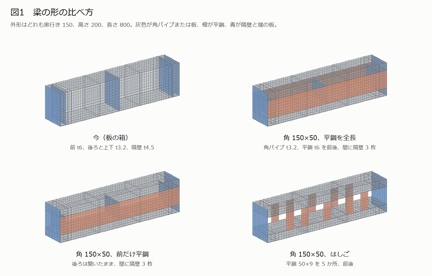
- We compared three layouts: flat bar covering the full length of both front and back faces, flat bar only on the front, and flat bar bridging five spots (a ladder layout).
- Bulkheads cannot be placed inside the square tubes, so they go between the tubes (behind the flat bar). Both ends are capped with t9 plates.
- Where flat bar overlaps the face of a square tube, it was modeled as a single plate with the combined thickness of the two.
Conclusion
- None of the combinations were lighter and stiffer than our current plate box.
- The stiffest option is adding full-length t6 flat bars to both the front and back, with 3 bulkheads inside. Tip front-back deflection goes from 0.0397 to 0.0371 (−6.5%), but the beam gets 13.6 kg heavier. If we simply increase the front plate of our current box from t6 to t9, it only adds 3.7 kg for a −5.3% reduction in tip front-back deflection (table in 6.8). For the same stiffness, making the current box thicker is lighter.
- The two inner walls of the square tubing (near the middle of the beam height) have little effect on both bending and twisting, so they do not add enough stiffness for their weight. The stiffness of the beam is determined by its 4 outer faces.
- Adding a flat bar only to the front leaves the back open, making it weak against torsion, and the front-back 200 N deflection increases by +15.4%. A ladder structure is even weaker, with tip front-back deflection at +33.5% and up-down at +26.7%.
- Without bulkheads, front-back 200 N deflection increases by 43.2%. If we close it off with flat bars, we must include the bulkheads between them.
- Ease of fabrication is not much different either. Because both edges of the flat bars are welded to the square tubing, there are 4 long weld seams across the front and back, the same as the 4 corner welds on our current box. In every design, the rail mounting surfaces need to be milled flat after welding.
We decided to stick with our current plate box. If we want to make the beam stiffer, we can increase the bulkheads from 3 to 5 (+2.0 kg, front-back 200 N deflection −2.9%), or make the front plate thicker.
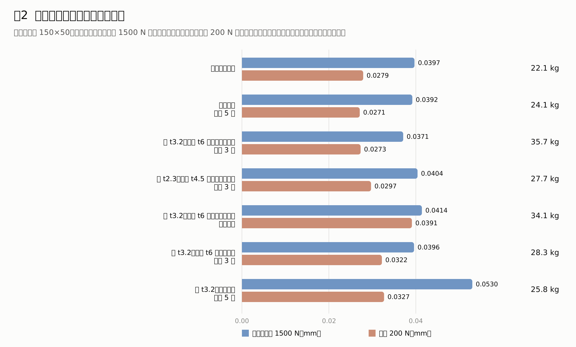
| Shape | Beam kg | Tip front-back | Tip up-down | Front-back 200 N | Left-right 200 N | Lowest natural frequency |
|---|---|---|---|---|---|---|
| Current (plate box, 3 bulkheads) | 22.1 | 0.0397 (+0.0%) | 0.0614 (+0.0%) | 0.0279 (+0.0%) | 0.0278 (+0.0%) | 71 Hz |
| Current box, 5 bulkheads | 24.1 | 0.0392 (−1.3%) | 0.0613 (−0.2%) | 0.0271 (−2.9%) | 0.0272 (−2.2%) | 70 Hz |
| Square t3.2, full-length t6 flat bar front and back, 3 bulkheads | 35.7 | 0.0371 (−6.5%) | 0.0592 (−3.6%) | 0.0273 (−2.2%) | 0.0272 (−2.2%) | 69 Hz |
| Square t3.2, full-length t6 flat bar front and back, 5 bulkheads | 36.8 | 0.0368 (−7.3%) | 0.0592 (−3.6%) | 0.0263 (−5.7%) | 0.0269 (−3.2%) | 69 Hz |
| Square t3.2, full-length flat bar front t6, back t4.5, 3 bulkheads | 33.9 | 0.0373 (−6.0%) | 0.0593 (−3.4%) | 0.0276 (−1.1%) | 0.0272 (−2.2%) | 69 Hz |
| Square t2.3, full-length t4.5 flat bar front and back, 3 bulkheads | 27.7 | 0.0404 (+1.8%) | 0.0616 (+0.3%) | 0.0297 (+6.5%) | 0.0281 (+1.1%) | 70 Hz |
| Square t3.2, full-length t6 flat bar front and back, no bulkheads | 34.1 | 0.0414 (+4.3%) | 0.0595 (−3.1%) | 0.0391 (+40.1%) | 0.0272 (−2.2%) | 69 Hz |
| Square t3.2, t6 flat bar front only, 3 bulkheads | 28.3 | 0.0396 (−0.3%) | 0.0601 (−2.1%) | 0.0322 (+15.4%) | 0.0277 (−0.4%) | 69 Hz |
| Square t3.2, ladder (50×9 flat bar at 5 locations, front and back), 5 bulkheads | 25.8 | 0.0530 (+33.5%) | 0.0778 (+26.7%) | 0.0327 (+17.2%) | 0.0348 (+25.2%) | 66 Hz |
| Square t3.2, ladder, no bulkheads | 23.1 | 0.0556 (+40.1%) | 0.0780 (+27.0%) | 0.0505 (+81.0%) | 0.0365 (+31.3%) | 66 Hz |
| Square 150×75×4.5, ladder, no bulkheads | 30.3 | 0.0464 (+16.9%) | 0.0650 (+5.9%) | 0.0417 (+49.5%) | 0.0292 (+5.0%) | 68 Hz |
Beam weight (kg) is the total of the square tubing or plates, flat bars, bulkheads, and end plates.
6.10 Extending the column ribs to the front face of the beam
The current ribs are triangles connecting the front face of the columns to the foot plates, with their upper ends at the bottom surface of the beam. We looked into extending them upward along the front face of the beam to directly connect the front face of the beam to the foot plates. The front end (on the foot plate, 210 from the front face of the beam) is kept unchanged. Calculations were done with the current design (steel base t12, surface height 0, tool 150, spindle at center of Y).
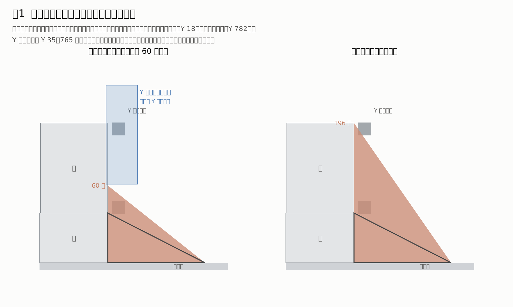
Conclusions
- Very effective. Extending both sides all the way to the top face of the beam reduces tip front-back deflection from 0.0397 to 0.0305 (−23.2%), with a weight increase of +2.9 kg. Per unit of weight, this is more effective than any of the plate thickness changes investigated in 6.8.
- The front column can only be extended up to 60 mm above the bottom surface of the beam. This is because the Y-axis belt cover sits in front of the beam at the same left-right position (Y 5 to 25). There is nothing in the way of the rear column.
- Practical extended design: front side extended 60 mm up, rear side extended to the top face of the beam. Tip front-back deflection is 0.0320 (−19.4%), up-down is 0.0575 (−6.4%), front-back 200 N is 0.0258 (−7.5%), left-right 200 N is unchanged, and weight is +1.9 kg. Even when refining the mesh to 7.5 mm elements, tip front-back deflection goes from 0.0421 to 0.0338 (−19.7%), showing the same trend.
- Combining this with the weight-reduction options from 6.8 allows us to increase stiffness while cutting weight. By thinning the frame ends, bulkheads, Z-axis walls, brackets, and foot plates while extending the ribs (Light 7), the structural frame becomes 6.2 kg lighter, and tip front-back deflection drops by −17.1%.
Why it works
When drilling thrust pushes the spindle upward, the beam twists as if tipping forward, bending the base of the columns. Because the current ribs only support the base of the columns, bending occurs at the corner of the beam's bottom surface. Extending the ribs up to the front face of the beam provides diagonal support to the front face directly from the foot plates, reducing this bending. This is the same reason the columns and ribs were so effective for their weight in Figure 2 of Section 6.8.
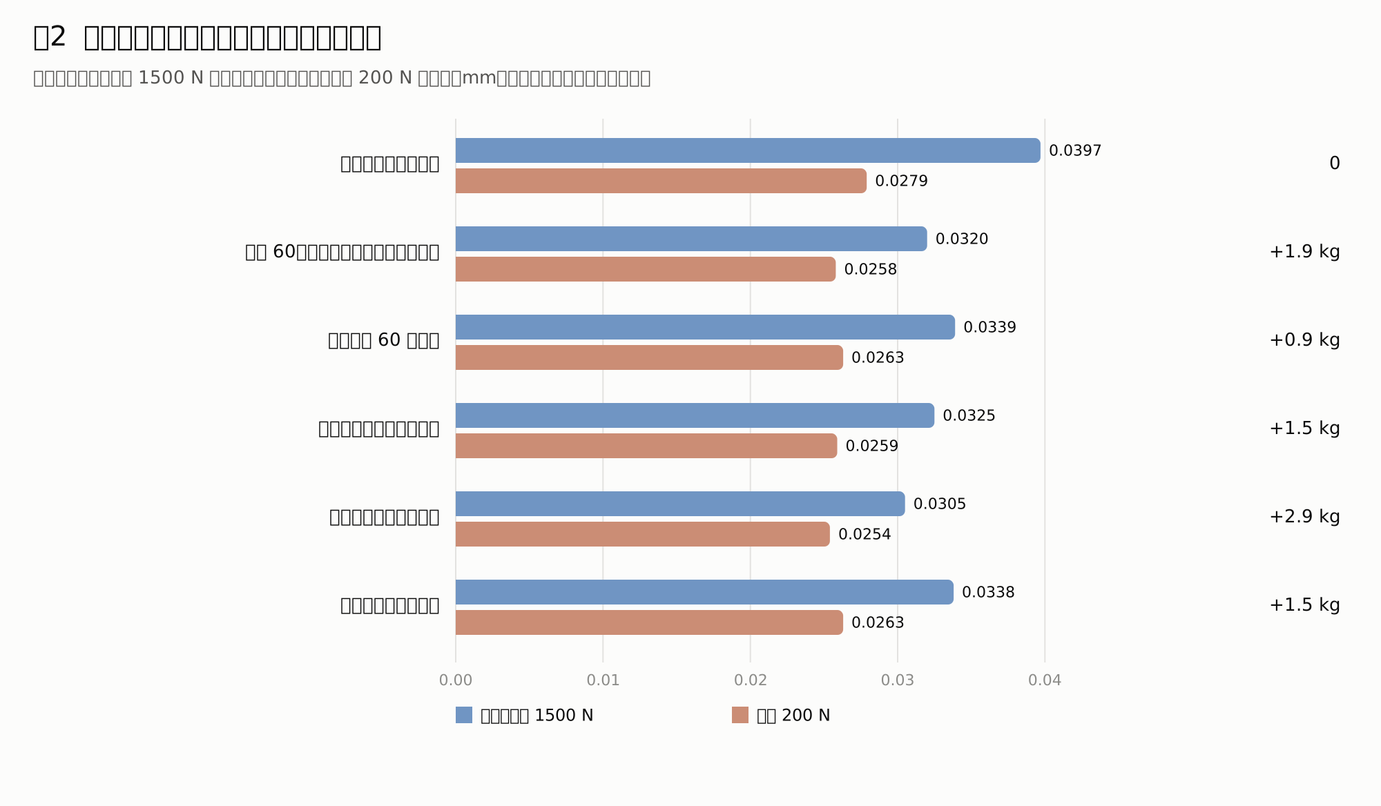
| Shape | Weight increase kg | Tip front-back | Tip up-down | Front-back 200 N | Left-right 200 N | Lowest natural frequency |
|---|---|---|---|---|---|---|
| Current (up to bottom of beam) | +0.0 | 0.0397 (+0.0%) | 0.0614 (+0.0%) | 0.0279 (+0.0%) | 0.0278 (+0.0%) | 71 Hz |
| Both sides up to 60 higher | +0.9 | 0.0339 (−14.6%) | 0.0585 (−4.7%) | 0.0263 (−5.7%) | 0.0277 (−0.4%) | 70 Hz |
| Both sides up to middle of beam | +1.5 | 0.0325 (−18.1%) | 0.0578 (−5.9%) | 0.0259 (−7.2%) | 0.0277 (−0.4%) | 70 Hz |
| Both sides up to top of beam | +2.9 | 0.0305 (−23.2%) | 0.0567 (−7.7%) | 0.0254 (−9.0%) | 0.0276 (−0.7%) | 70 Hz |
| Both sides up to top of beam, rib t12 | +4.4 | 0.0301 (−24.2%) | 0.0566 (−7.8%) | 0.0253 (−9.3%) | 0.0276 (−0.7%) | 70 Hz |
| Back side only up to top of beam | +1.5 | 0.0338 (−14.9%) | 0.0585 (−4.7%) | 0.0263 (−5.7%) | 0.0277 (−0.4%) | 70 Hz |
| Front 60, back up to top of beam | +1.9 | 0.0320 (−19.4%) | 0.0575 (−6.4%) | 0.0258 (−7.5%) | 0.0277 (−0.4%) | 70 Hz |
Combining with the lightweighting options from 6.8
| Shape | Weight increase kg | Tip front-back | Tip up-down | Front-back 200 N | Left-right 200 N | Lowest natural frequency |
|---|---|---|---|---|---|---|
| Light 6 + extended ribs | −2.7 | 0.0320 (−19.4%) | 0.0573 (−6.7%) | 0.0262 (−6.1%) | 0.0275 (−1.1%) | 72 Hz |
| Light 7: Light 2 + foot plate t12 + extended ribs (legs and ribs at current thickness) | −6.2 | 0.0329 (−17.1%) | 0.0579 (−5.7%) | 0.0265 (−5.0%) | 0.0280 (+0.7%) | 71 Hz |
| Light 2 + extended ribs (legs and ribs at current thickness) | −4.1 | 0.0326 (−17.9%) | 0.0577 (−6.0%) | 0.0263 (−5.7%) | 0.0279 (+0.4%) | 71 Hz |
The extended-rib shape is "Front 60, back up to top of beam". Light 2 has frame ends t1.6, bulkheads t3.2, Z walls t4.5, and mounts t16.
We recommend Light 7 (replacing Light 6 from 6.8). The frame becomes 6.2 kg lighter, just like Light 6, and the tip front-back displacement is even smaller at 0.0329 compared to 0.0380 for Light 6. The legs and ribs can stay at their current thicknesses (legs: rectangular tube 150×75×3.2, ribs: t9), so there is no need to fabricate the legs out of plate. Only the displacement under left-right 200 N increases slightly by +0.7%.
Notes
- When moving Y all the way to the front (spindle Y 160), the front rib has only about 3.5 mm of clearance to the Y carriage block on the left and right. Either shift the rib 5 mm forward (Y 13) or reduce the Y travel by 5 mm. The back rib has about 27 mm of clearance.
- At the height of the lower rail, the back rib projects forward by about 125 mm from the front face of the beam. It does not collide with the Y carriage or blocks because its left-right position is different, but keep it clear of wiring and cable routing paths.
- Because the rib shapes differ between left and right, the displacement when the spindle is at the ends of the Y axis may vary slightly between left and right. The calculations only cover the case where the spindle is at the center of Y.
- If the Y belt cover can be moved to the opposite end (the back), both sides can be extended to the top of the beam (tip front-back −23.2%). This requires changing the motor and belt layout.
6.11 Results before adopting Light 7 (N1)
Legs 105, Z stroke 150, no Z front plate, steel table t12. Units in mm.
When machining a plate on top of the base stand
Base stand height 50, plate placed on top of a backing plate. t32 was solved using W 31 (W 29 had mesh nodes that did not connect).
| Plate | Tool | Tip front-back | Tip up-down | Front-back 200 N | Left-right 200 N |
|---|---|---|---|---|---|
| t9 (W 6) | 150 | 0.039 | 0.139 | 0.028 | 0.028 |
| t9 (W 6) | 130 | 0.044 | 0.140 | 0.031 | 0.030 |
| t32 (W 31) | 150 | 0.037 | 0.139 | 0.025 | 0.027 |
| t32 (W 31) | 130 | 0.037 | 0.139 | 0.025 | 0.027 |
About 0.075 of the up-down value is the deflection of the base stand plate, which is the value when supported at only 12 points on the bottom surface. This is expected to be smaller when placed on a workbench. It does not affect through-holes.
Differences by spindle height (tool 150, no base stand)
| Operating position | Tip front-back | Tip up-down | Front-back 200 N | Left-right 200 N |
|---|---|---|---|---|
| Surface height 0 | 0.040 | 0.061 | 0.028 | 0.028 |
| Surface height 50 | 0.034 | 0.062 | 0.022 | 0.025 |
| Spindle at top | 0.030 | 0.062 | 0.018 | 0.023 |
| Spindle at bottom | 0.052 | 0.062 | 0.043 | 0.034 |
| Surface height 0, guides 100 N/µm | 0.056 | 0.069 | 0.041 | 0.039 |
| Surface height 0, guides 400 N/µm | 0.031 | 0.057 | 0.021 | 0.022 |
Natural frequencies
At surface height 0: 71, 90, 108, 153, 198 Hz. Avoid spindle speeds close to the tooth pass frequency. For a 2-flute tool, 72 Hz corresponds to about 2150 rpm.
6.12 Effectiveness of each member (before deciding on the legs)
We investigated this using the baseline design (model 111.5 kg) before deciding on the legs and stroke. The underlying behavior is the same for the current design.
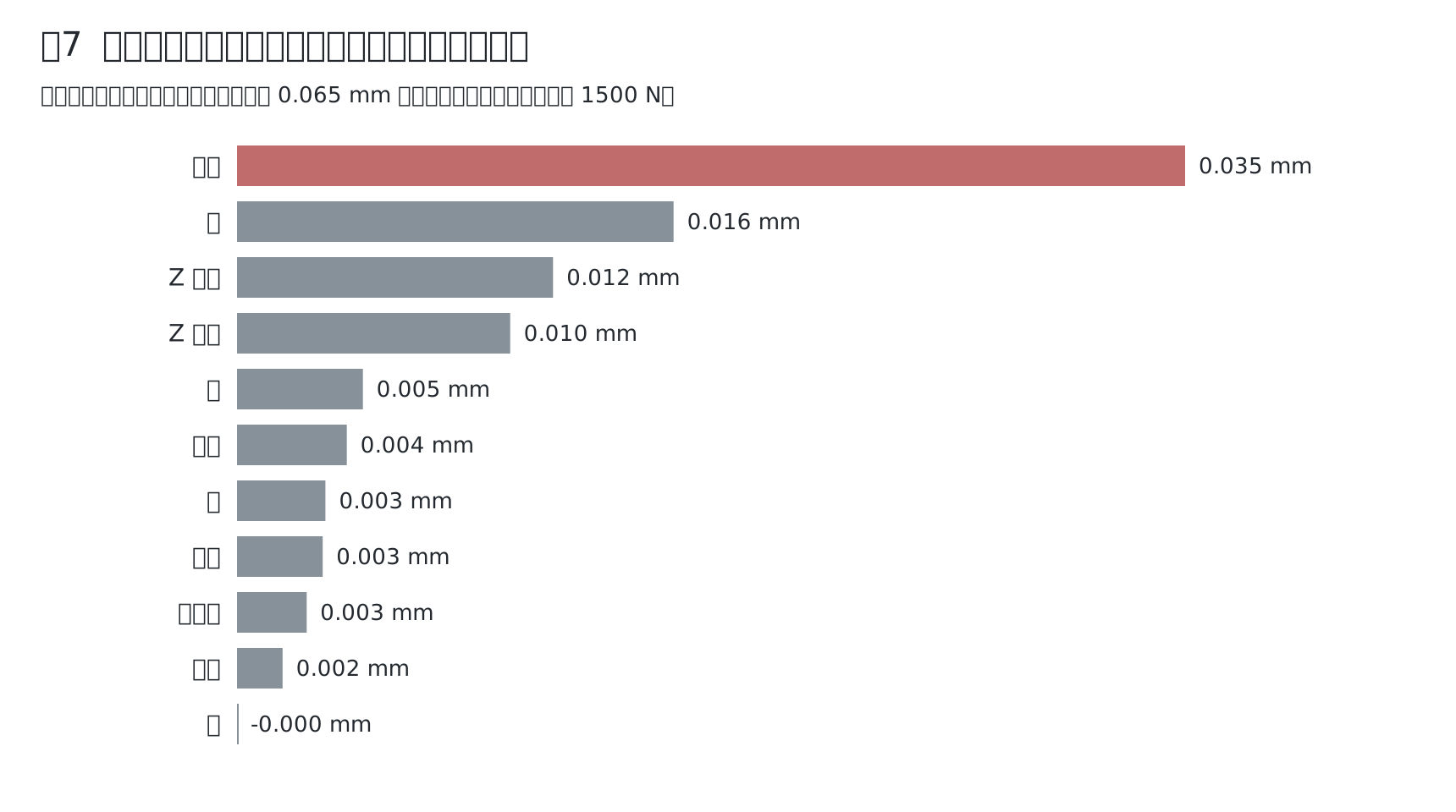
This shows how much the displacement decreases when increasing the stiffness of only that member by 100 times. The guides are the most significant, followed by the beam, then the Z walls and plates. The frame barely has any effect, though this is partly because the supports were assumed to be fixed.
| Change | Tip front-back | Front-back 200 N |
|---|---|---|
| Baseline | 0.065 | 0.063 |
| Z plate is a single aluminum t20 plate (no box) | 0.951 | 0.602 |
| Z plate is a single steel t20 plate (no box) | 0.388 | 0.259 |
| Single head mount plate | 0.075 | 0.071 |
| No leg ribs | 0.130 | 0.085 |
| No beam bulkheads (end plates only) | 0.086 | 0.115 |
6.13 Which edges to weld on the bulkheads inside the beam
Since the beam is closed by joining the front plate to the channel, the internal bulkheads cannot have all their edges welded from the inside. Using the current design (Sections 1 to 5), we solved for different welded edges on the 3 internal bulkheads. The edges that were not welded were offset 15 away from the beam plate so they would not connect.
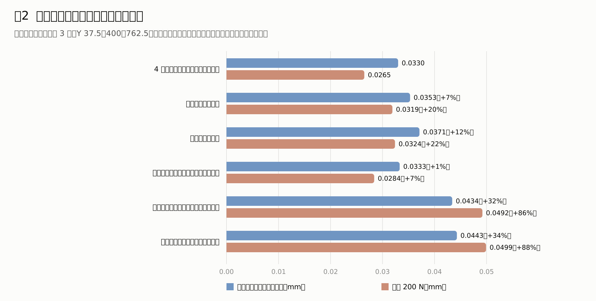
| Welded edges | Tip front-back | Front-back 200 N |
|---|---|---|
| All 4 edges welded (assumption of current calculations) | 0.0330 (0%) | 0.0265 (0%) |
| Back edge not welded | 0.0353 (+7%) | 0.0319 (+20%) |
| Front edge not welded | 0.0371 (+12%) | 0.0324 (+22%) |
| Top and bottom edges not welded (front and back only) | 0.0333 (+1%) | 0.0284 (+7%) |
| Only front edge welded (back, top, and bottom not welded) | 0.0434 (+32%) | 0.0492 (+86%) |
| No internal bulkheads (only end plates) | 0.0443 (+34%) | 0.0499 (+88%) |
- The role of the bulkheads is to maintain the cross-sectional shape of the beam. Connecting the front plate and the back plate is what matters; the top and bottom edges have little effect.
- A bulkhead welded only on the front edge is almost the same as having none at all.
- We decided on an assembly method where the front edge is welded from both sides, and the back edge is welded through slots in the back plate (see "Beam Assembly Method" in Parts List and Dimensional Drawings).
6.14 Lateral Position of the Leg Ribs
We solved with the leg ribs moved to the outer edge, center, and inner edge of the leg square tubing (width 75). Based on the current design (Sections 1 to 5), the far leg has these positions mirrored left-to-right.
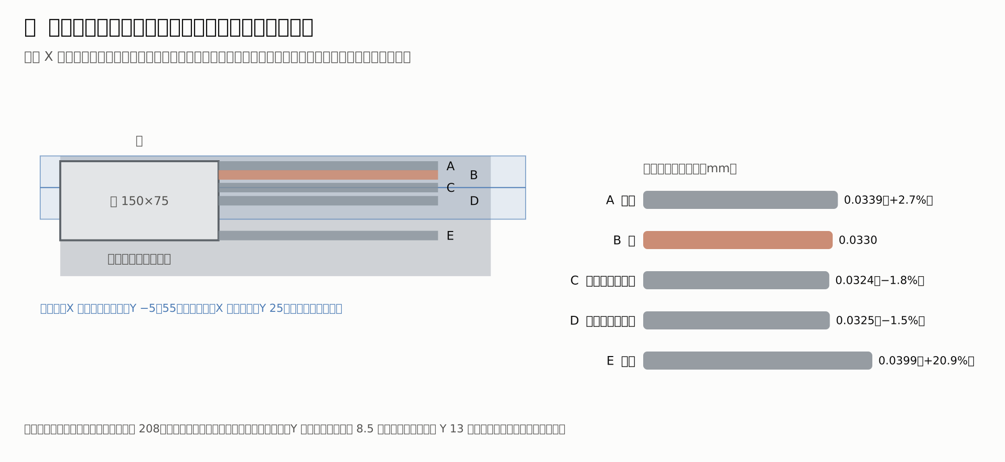
| Rib position | Tip front-back | Front-back 200 N | Left-right 200 N |
|---|---|---|---|
| Current (near Y 13, far Y 782) | 0.0330 (0%) | 0.0265 (0%) | 0.0280 (0%) |
| Shifted to outer edge (near Y 4.5, far Y 795.5) | 0.0339 (+3%) | 0.0267 (+1%) | 0.0279 (0%) |
| Flush with outer wall (near Y 2.25, far Y 797.75) | 0.0348 (+5%) | 0.0269 (+2%) | 0.0279 (0%) |
| Directly above block (near Y 25, far Y 775) | 0.0324 (−2%) | 0.0264 (0%) | 0.0281 (0%) |
| Only far side directly above block (near Y 13, far Y 775) | 0.0327 (−1%) | 0.0265 (0%) | 0.0280 (0%) |
| Center of square tubing (near Y 37.5, far Y 762.5) | 0.0325 (−2%) | 0.0265 (0%) | 0.0282 (+1%) |
| Shifted to inner edge (near Y 70.5, far Y 729.5) | 0.0399 (+21%) | 0.0284 (+7%) | 0.0282 (+1%) |
- Shifting the rib to the outer edge of the square tubing makes it slightly worse (+3%). Moving it flush with the outer wall gives +5%.
- What matters is whether the rib sits above the X blocks under the foot plate (near Y −5 to 55, far Y 745 to 805). As long as it is over the block, the positional difference is within 2%; once it leaves the block, the foot plate flexes and performance drops significantly (+21% at the inner edge).
- The near rib has only 8.5 of clearance to the Y carriage, so it can barely be moved inward from where it is now. The far side can be moved directly above the block (Y 775), but the effect is only −1%, so we kept the current positions.
6.15 Moving the legs and ribs toward the center of the X blocks
We moved the leg square tubes (width 75) and ribs toward the center of the X blocks under the foot plates (front Y 25, back Y 775). Since the legs stick out 12.5 past the frame, we also extended the beams by 12.5 on both sides to 825, and moved the internal bulkheads to the center of the blocks (Y 25, 775) as well. We solved this with the current configuration (Sections 1 to 5).
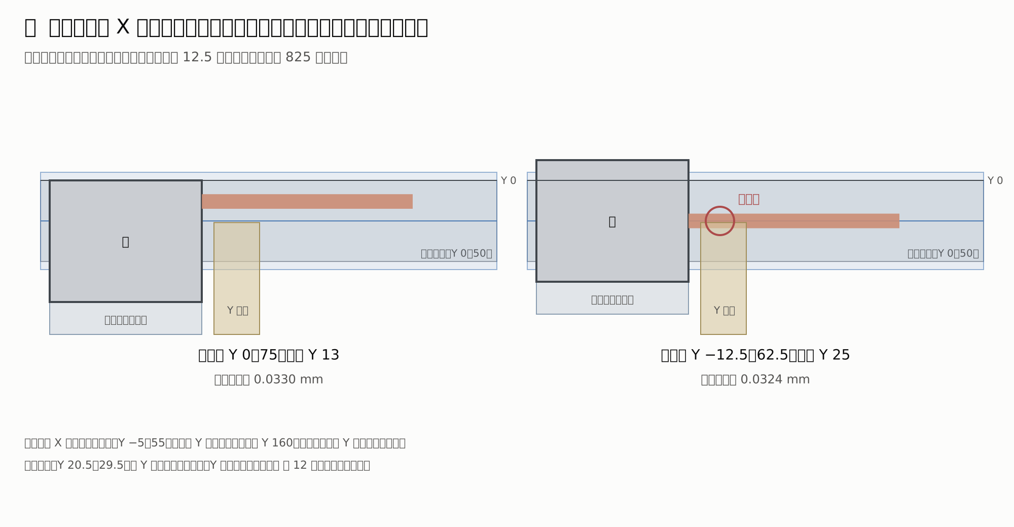
| Shape | Tip front-back | Front-back 200 N | Left-right 200 N | Weight kg |
|---|---|---|---|---|
| Current | 0.0330 (0%) | 0.0265 (0%) | 0.0280 (0%) | 0 |
| Legs and ribs at block centers (beam 825) | 0.0324 (−2%) | 0.0266 (0%) | 0.0281 (0%) | +0.3 |
| Legs at block centers, front rib kept at Y 13 (beam 825) | 0.0328 (−1%) | 0.0267 (+1%) | 0.0281 (0%) | +0.3 |
| Legs kept as-is, only ribs at block centers | 0.0324 (−2%) | 0.0264 (0%) | 0.0281 (0%) | 0 |
- Even if we move the leg square tubes, the deflection barely changes. The only thing that has an effect is the rib position, and even that is just −2%.
- If we place the front rib at Y 25, it hits the block of the Y carriage when Y is moved all the way forward. We would need to reduce the Y travel range by about 12 at the front.
- The beams stick out past the frame, increasing the overall width from 800 to 825.
- It isn't worth changing the travel range and overall width for just 2%, so we decided to keep the current shape as it is.
7. Terminology and Model
Terminology and Coordinates
| X | Front-back direction. Rear edge of the frame is 0, front edge is 1000 |
| Y | Beam direction. Near side of the frame is 0, far side is 800 |
| Height | Bottom surface of the frame is set to 0 |
| Spindle nose | Bottom end of the head. The tool holder extends from here |
| Tool length L | From the spindle nose to the tool tip |
| Surface height W | Height of the surface being machined. W + L gives the height of the spindle nose |
| Tip front-back, up-down | Deflection at the tool tip under 1500 N of drilling force (thrust) |
| Front-back 200 N, left-right 200 N | Deflection in the same direction when a 200 N lateral force is applied to the tool tip. Reference value for milling |
Model
| Item | Details |
|---|---|
| Analysis tool | CalculiX 2.22 (bundled with FreeCAD 1.1). Models are built in Python. |
| Elements | 4-node shell S4, approx. 15 mm. Approx. 14,000 nodes, approx. 14,000 elements. |
| Materials | Steel 205 GPa, aluminum 70 GPa, Poisson's ratio 0.3, 0.33 |
| Guides | Each block is modeled as a 200 N/µm spring (assumed). There are no values in the catalog. |
| Ball screws | 40 N/µm spring per screw. Calculated value for the screw, nut, and bearings in series. |
| Head | Rigid body. Connected by the upper and lower support plates. |
| Support | Fixed at 12 points on the bottom surface of the stand. For comparison without the stand, fixed at the bottom surface of the frame. |
| Force | With the stand, forces push against each other between the tool tip and the plate. The results show the relative displacement between the two. |
What Is Not Included
- Actual guide rigidity and play. Welding distortion. Bolt loosening (welds and plate joints are assumed to be fully bonded).
- Spindle bearing deformation, bending of the tool itself, and deformation of the plate and jig.
- Rigidity of the rails and reference stops (we did not add this, so it stays on the safe side).
- Spindle motor position (mass was included in the head). Details of the X nut mount.
8. What We Verified
- Torsion of a single beam: The finite element method average of 5.13×10⁻⁵ rad matched our hand calculations (Bredt's formula) (beam 200×150×4.5, length 800, torsional moment 1500 N × 288 mm).
- Mesh: The difference between 15 mm and 10 mm was about 4–5%. A 15 mm mesh is sufficient for comparisons. We treat absolute values as slightly larger.
- Node connections: We verified that the members are split into four chunks (frame, gantry, table, Z) and connected only by the guide springs.
- Unsolvable cases (Z4, W 29): The grid lines were too close, so the nodes failed to connect. You can tell because the displacement reaches the 10⁸ mm range. We did not use those values.
- Even with the current shape, verifying with 7.5 mm elements showed only about a 5% difference compared to 15 mm (6.10). A 15 mm mesh is enough for comparisons.
- The rear rib collided with the Y ball screw, so we shortened the screw length so it only sticks out 15 beyond the supported-side bearing (BF12) (verified in the 3D model).
9. How to Reproduce
The models and calculation scripts are located in analysis/fea in the repository.
| File | Description |
|---|---|
| gantry_legc.py, legc_fig.py | 6.15 plan and figures for bringing the legs and ribs closer to the block centers |
| gantry_ribpos.py, ribpos_fig.py | 6.14 left/right rib positions and figures |
| gantry_bulk.py, beam_build_fig.py | 6.13 bulkhead weld edges and beam assembly figures |
| gantry_now.py, now_fig.py | Sections 1–5 (current shape, cases where we drop decisions one by one, rejected ideas, and effect of each part) and figures |
| gantry_fea.py | Generates models from dimensions and solves them with CalculiX |
| gantry_plans.py, gantry_zplans.py, gantry_best.py | Solves the proposals in 6.1–6.3 in order |
| gantry_near.py, gantry_n1.py, gantry_steel.py, gantry_stand.py, clamp_fea.py | Legs, current proposal, table material, stand, plate clamping methods |
| n1base.py, gantry_holes.py, gantry_sens.py, gantry_sens2.py, gantry_light.py, gantry_light2.py, gantry_light3.py, gantry_stress.py, gantry_twin.py, gantry_twin2.py, gantry_rib.py, gantry_rib2.py, gantry_rib3.py | 6.8 lightening holes, plate thickness, stress, 6.9 beam shapes, 6.10 ribs |
| plan_cards.py, fea_view.py, light_fig.py, light_fig2.py, twin_fig.py, rib_fig.py | Plots the result figures |
| *.json | Numerical results |
QR code for this page
https://robo100.jp/en/000015
No comments yet.