Machine Shape and Dimensions
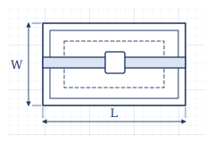
An explanation of the current design. For comparisons between design options and the rationale behind the numbers, see the structural analysis calculation sheet. Purchased parts are shown as provisional shapes simplified into boxes or cylinders. Height is referenced with 0 at the bottom surface of the frame, with units in mm.
Overall Shape
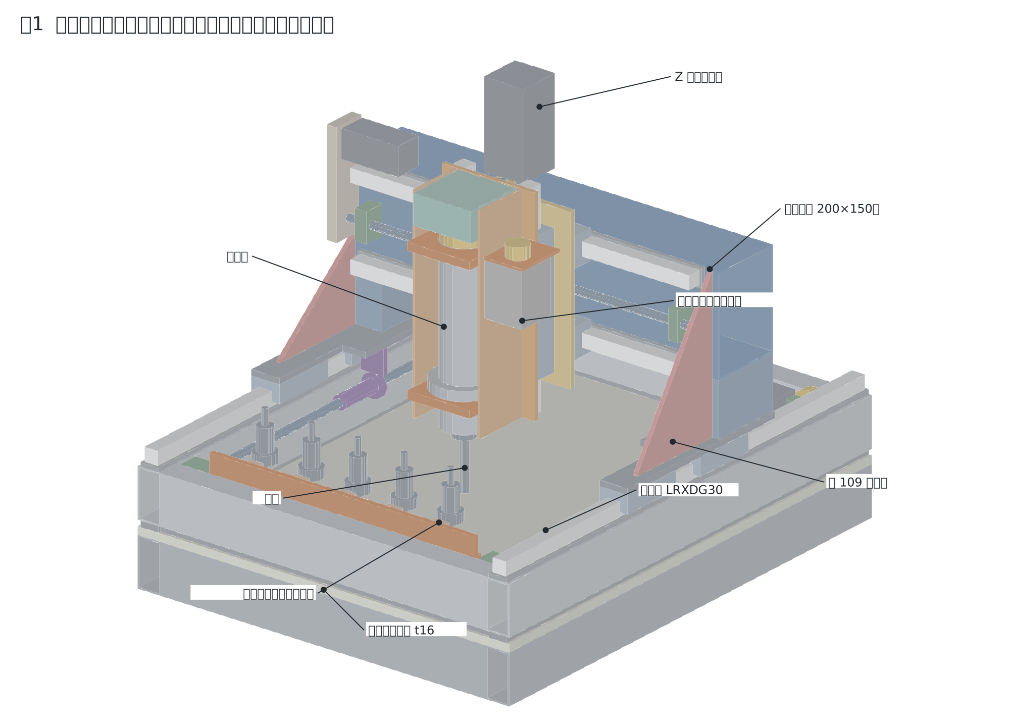
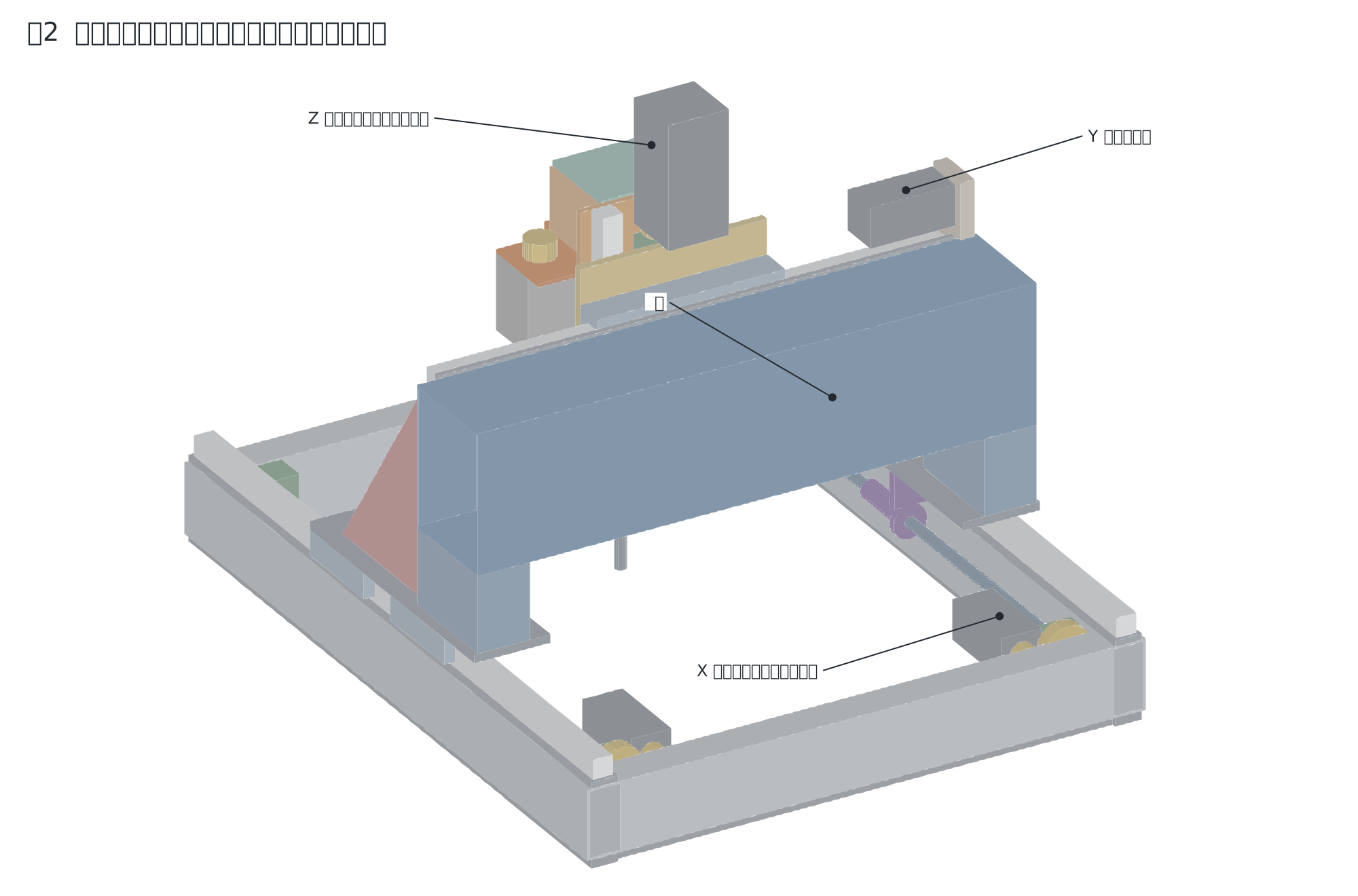
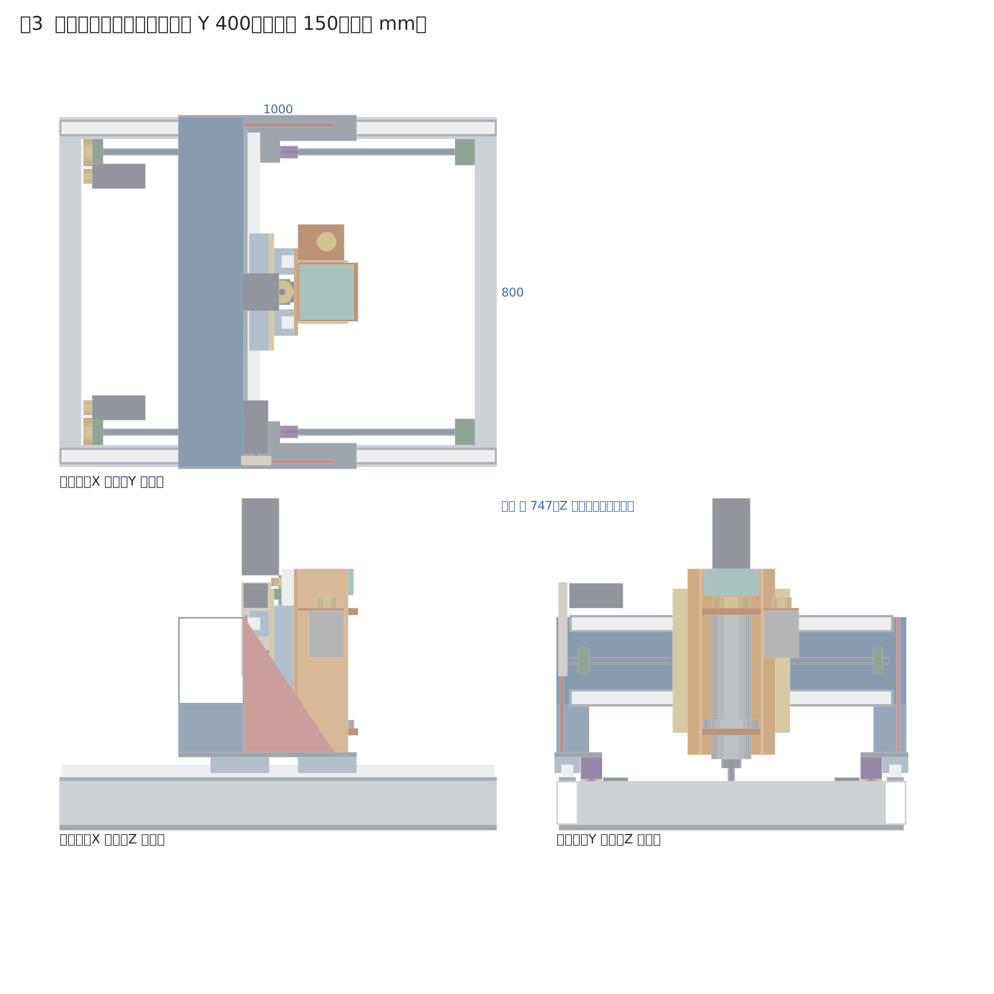
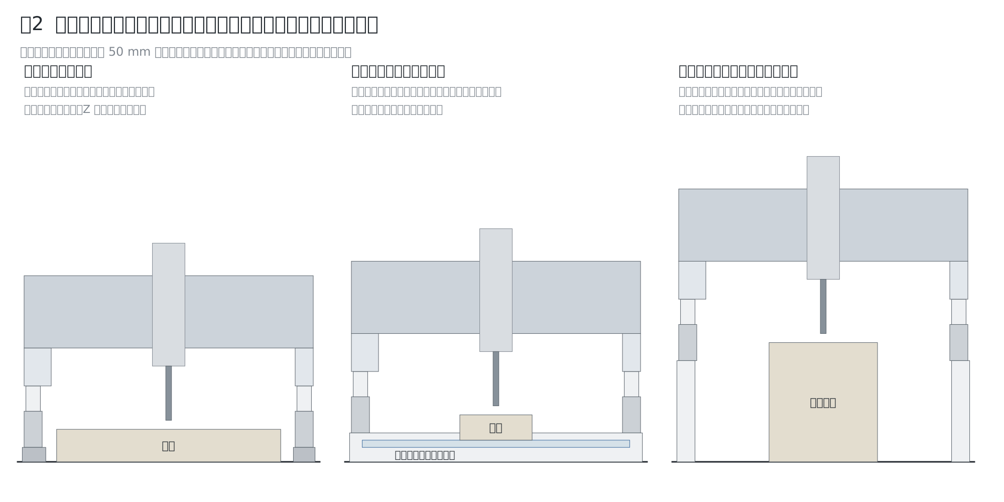
The gantry (legs and beam) moves front-to-back over the frame (X), the carriage moves left-to-right in front of the beam (Y), and the Z box and head move up and down in front of the carriage (Z). The bottom side is open, so workpieces and plates fit inside the frame.
Main Dimensions
| Part | Details |
|---|---|
| Frame | 100×50 rectangular tubing (t3.2 long sides, t1.6 ends), outer dimensions 1000×800. 38×12 pads underneath, 38×9 backing strips on top |
| Legs | 150×75×3.2, height 109. Foot plate t12 underneath. Front rib t9 (rear extends to top surface of beam, front extends to 60 above bottom surface of beam) |
| Beam | Folded and assembled sheet metal 200×150, length 800. Front t6, others t3.2, 5 bulkhead plates t3.2 |
| Carriage | Steel t12, 268×330 |
| Z box | Plate t9 200×425, walls t4.5 depth 120. Cover on front |
| Head mount | t16, 2 plates (top and bottom), 280 spacing |
| Guides | LRXDG30. X 990×2, Y 730×2, Z 425×2, 12 blocks |
| Feed | Ball screw DFU1605, motor folded back with belt |
Travel Range
| Direction | Range | Amount |
|---|---|---|
| X (front-to-back) | 270 to 926 (283 to 805 with rack attached) | 656 (522) |
| Y (left-to-right) | 160 to 616 | 456 |
| Z (spindle nose height) | 80 to 230 | 150 |
Lower Limit of the Spindle Nose
Lowering the spindle nose causes interference with parts at the edges of the machine. Using the 3D model, we checked combinations of 4 front-to-back positions, 4 left-to-right positions, and 4 height positions.
| Location | Interfering Part | Spindle Nose Lower Limit |
|---|---|---|
| Front edge (forward of X 892) | Frame edge, head, and tool | 120 |
| Y edges (188 or less, 588 or more) | X nut and bearings, Z rails and wall | 100 |
| Rear corners (X 307 or less, Y edges) | X motor and Z rails | 110 |
| Other | None | 80 |
LinuxCNC soft limits use a simple bounding box, so we set the lower limit to 120 across the full range, and switch settings when we want to lower it only in the center. Verified with a 125 mm tool, there is no interference across the entire range as long as the spindle nose is at 120 or higher.
Using the Spindle Close to the Beam
Deflection at the tool tip increases the further the spindle gets from the Z blocks. Most workpieces are plates, and the clearance between the beam and the workpiece can be small, so we shortened the legs and use the spindle close to the beam.
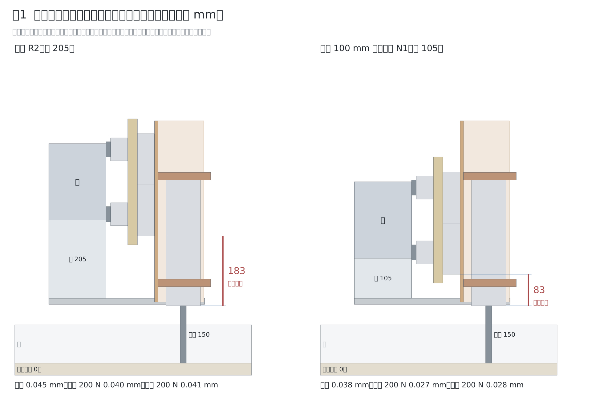
For tall workpieces, we swap out the base stand to lift the entire machine.
Storage Height
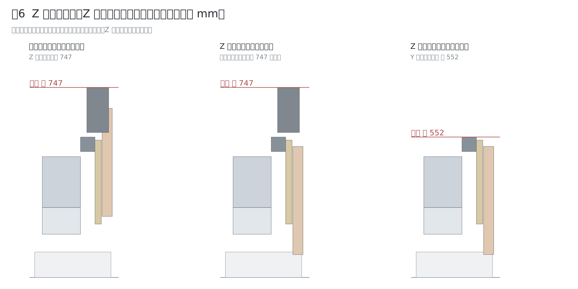
The Z motor is fixed to the carriage, so just lowering Z does not make it shorter. For storage, rest Z on the lowest stop and remove the Z motor (4 bolts and the belt). The brake also comes off with the motor, so be sure to rest it on the stop before removing it. Re-home the machine after reinstalling.
Weight
| Framework (frame, legs, beam, carriage, Z) | 74.7 kg |
| Linear guides (4.29 m rails, 12 blocks) | 35.7 kg |
| Backing strips | 9.4 kg |
| Head, cylinder, spindle servo | 32 kg |
| Ball screws, feed motors, pulleys | 21 kg |
| Wiring, piping, covers (rough estimate) | 16 kg |
| Total | Approx. 189 kg |
We decided on the plate thickness of the framework and the rib shapes after calculating their effectiveness. For what changes and how, see sections 3 and 4 of the structural analysis calculation sheet.
Layout Notes
- The X screw runs at a height of 80, which is lower than the top surface of the frame. This is because the Z box passes over the screw at the ends of Y travel.
- The leg ribs extend along the front face of the beam. On the front side, because the Y belt cover is located at the same left-to-right position on the front of the beam, the rib only extends up to beneath the cover (60 above the beam's bottom surface). When Y is brought all the way forward, the clearance between the front rib and the carriage is 8.5.
- The Y screw length extends 15 past the supported-end bearing (BF12) (total length approx. 755). This prevents it from hitting the rear rib.
- Because we made the foot plate t12, we made the legs 109, keeping the height above the beam unchanged.
- We use 32T and 16T for the Z pulleys. A 40T pulley does not fit into the 45 mm clearance between the carriage and the Z plate. For the nut flange (φ48), we use a double-flat shape (width 40) and machine clearance on the carriage side.
- The spindle motor is planned to be placed next to the head (Y +115).
- If the Z belt snaps, the brake will not work and the spindle will drop. We will consider a counterweight cylinder or a brake on the screw side. Never put your hands under the tool.
- If the X belt snaps, no motor alarm will trigger. Detect it by sensing screw rotation or checking the origin.
Unverified Items
- Routing paths for wiring and piping, and covers. Mounting holes for purchased parts.
- Actual rigidity and play of the linear guides.
- Z motor drawings and torque curve.
- Since we made the head mount t16, whether the clamping length for the spindle is sufficient (to be decided when settling on the head mounting method).
- Since we made the foot plate t12, whether the thread engagement depth for the screws fastening the X blocks is sufficient.
QR code for this page
https://robo100.jp/en/000014
No comments yet.