Tool Change Rack
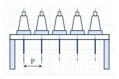
A shelf where tool holders are placed upright for storage. The spindle moves itself to a receiver, puts down the tool, and grabs the next one. There is no tool changer arm; tools are swapped using only X, Y, and Z movements. The dimensions here are a proposal, and the holder values are typical BT30 numbers. Heights are measured with the bottom face of the frame as 0, and all units are in mm.
Summary
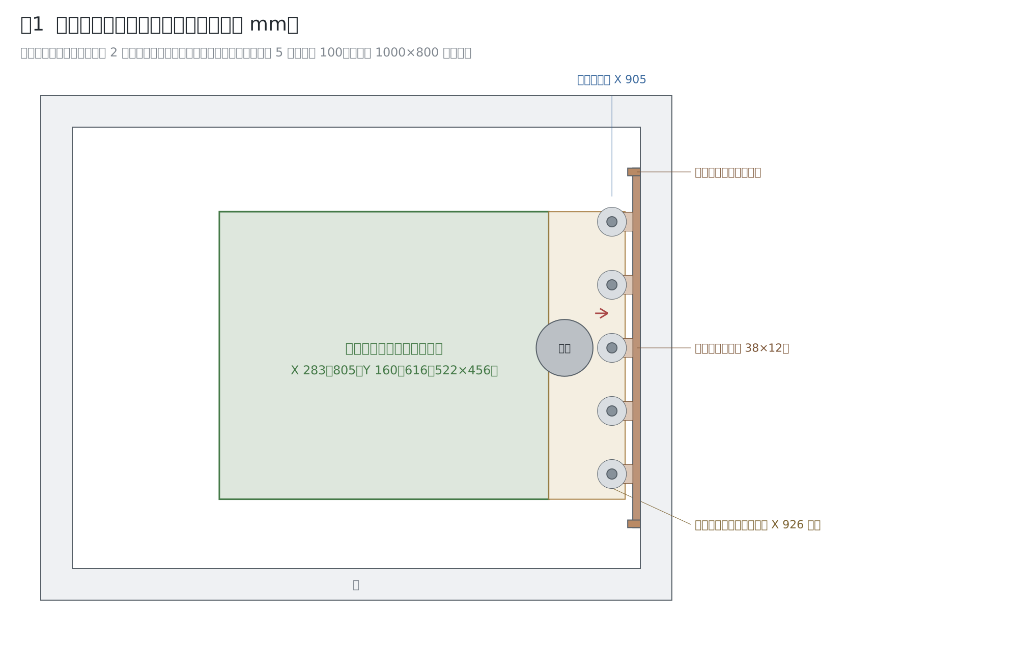
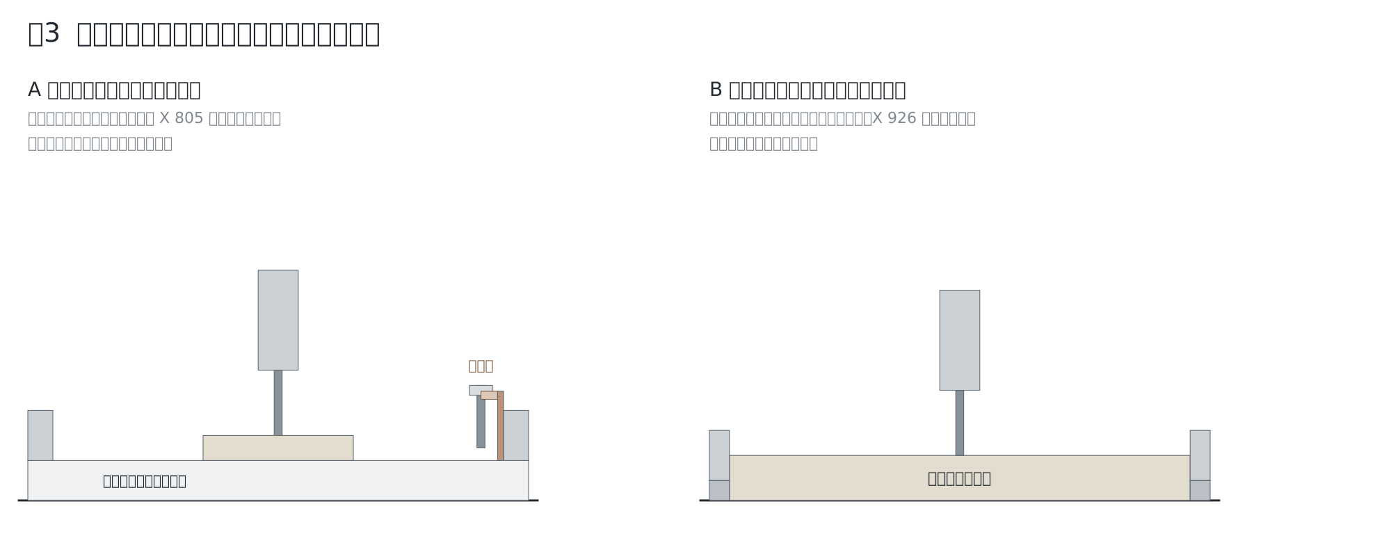
- We attach the rack to the stand rather than the machine itself. When placing the machine directly on a workpiece, we only need to transport the machine, so no disassembly is required.
- The receiver bar is supported at both ends by two posts rising from the stand, keeping it inside the frame. The entire setup fits within 1000×800.
- It holds 5 tools. The receiver height is approx. 130, spacing is 100, and the positions are Y 200, 300, 400, 500, and 600.
Tool Change Sequence
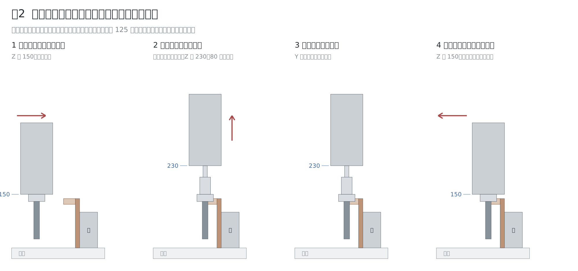
- Set the spindle nose to 150 and enter the empty receiver from the side. The receiver clamps the holder's groove.
- Release the tool and raise the spindle nose to 230. Since the height of the holder taper and pull stud is approx. 71, we raise it by 80.
- Move along Y directly above the next tool.
- Lower to 150 to clamp the tool, then slide it out sideways.
With or Without Stand
| Mounted on the stand | Mounted on the workpiece | |
|---|---|---|
| Tool change | Automatic | Manual (release with a button) |
| Spindle X range | 283 to 805 | 270 to 926 |
Basis for Dimensions
- The receiver bar uses 38×12 flat bar steel oriented vertically, placed at X 938 to 950 and Y 115 to 685. Distributing the 75 N load of 5 tools across the total span, the deflection is 5 × 75 × 570³ / (384 × 205000 × 54,900) = approx. 0.02 mm.
- The receiver center is at X 905. There is an 8 mm gap between the holder nut radius (25) and the bar. The upper limit for tool diameter is approx. φ60.
- The X position of 805 is calculated by starting from the receiver center (905) and subtracting the lower head support plate protrusion (72), the holder radius (23), and a margin of 5.
- The posts are located at Y 115 to 127 and Y 673 to 685. We avoided the supported-side bearing of the X lead screw. We checked in the 3D model that there is no interference.
Number of Tools
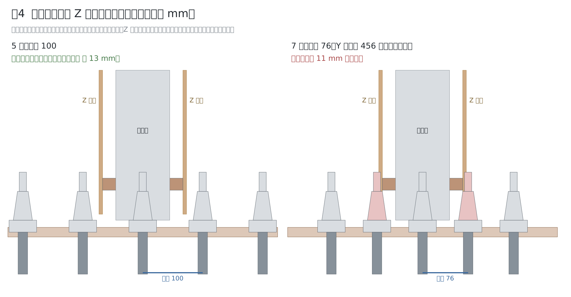
When the spindle enters the receiver, the bottom edge of the Z wall sits at 160. The taper of an adjacent parked tool reaches above this height, so if the spacing is too tight, it will hit the wall. The required spacing is the outside of the wall (73) + the taper radius (14.4) = 87.4, plus some clearance.
| Tools | Pitch (within Y 456) | Clearance to wall | Decision |
|---|---|---|---|
| 5 | 100 | 12.6 | Adopted |
| 6 | 91 | 3.6 | Margin is small |
| 7 | 76 | −11.4 | Interferes |
A rotary rack would allow holding more tools, but that adds an indexing mechanism and another axis.
Height Constraints
The tip of a parked tool sits at 150 − tool length. For a 150 tool it is 0, for 125 it is 25, and for 100 it is 50. Since the bottom of the tool is lower than the top surface of the frame, do not place any parts under the tool parking locations.
Pending / Unconfirmed
- Shape of the receiver (spring clip or plastic). We need to check the actual holder V-groove dimensions on physical parts.
- Measures against chips sticking to the receivers and holders (covers or air blow).
- Procedure for confirming receiver positions when remounting the machine on the stand.
- Spindle orientation. We need to check on the physical head whether we need to align the holder keyways.
QR code for this page
https://robo100.jp/en/000019
No comments yet.