How to Use Rigid Tapping
2026-11-05. I investigated and decided on how to use rigid tapping on this machine (7I76EU, spindle is A6-RS with a 2:1 ratio, and Z is a closed-loop stepper). I read the official documentation and forums. I also used Gemini searches as clues. I only used answers from Gemini that were verified against original sources. [Source] means official documentation or product literature. [Forum] means user reports. [Calculation] means an estimate based on assumptions.
Conclusions
- Use G33.1. Do not use G84. In LinuxCNC, G84 does not synchronize with the spindle. It is a cycle intended for using a floating holder and stopping at the bottom of the hole. [Source]
- A 1-pulse-per-revolution spindle sensor is definitely necessary. When repeating G33.1 in the same hole (pecking), the position aligns using the index. Because the servo's Z phase triggers twice per spindle revolution, it cannot be used for the index.
- At the bottom of the hole, it overshoots about 0.4 to 0.8 mm deeper than commanded. This is roughly constant regardless of the tap diameter. For blind holes, make the pilot hole deeper by this amount plus the lead chamfer. [Calculation]
- We buy one synchro holder (with micro-float). We decided not to clamp a round shank in a regular ER collet.
- M3 to M8 are for regular use. M10 can be used for short runs. For M12 and larger, use a thread mill. This follows our policy so far. Spindle torque is kept to about 12 N·m by the servo's torque limit. Since M10 in S45C can exceed this limit, thread milling is the first choice.
- Initially, start with through-holes at a cutting speed of 5 m/min (160 rpm for M10).
- Thread milling does not require synchronization. The pitch is determined by helical interpolation of X, Y, and Z, while the spindle simply spins. You can use it before rigid tapping is up and running, and the thread diameter can be adjusted later (Section 7).
1. Rigid Tapping in LinuxCNC (G33.1)
The syntax is G33.1 Z- K- I- $-. [Source]
| Word | Meaning |
|---|---|
| Z | Commanded depth. Move XY to the hole position on the preceding line. Write only Z in G33.1. Writing XY results in coordinated diagonal motion. |
| K | Feed per revolution. For metric threads, this is the pitch (K1.5 for M10). Do not write F. |
| I | Spindle speed multiplier on retract (optional). |
| $ | Spindle number (optional). |
Sequence of motion (from the official documentation). [Source]
- Waits for spindle index, then feeds down to the commanded depth synchronized with spindle rotation.
- Commands spindle reversal at the commanded depth (increases speed if I is specified).
- Until the spindle actually stops and reverses, it continues past the commanded depth while remaining synchronized.
- Retracts to the starting height synchronized with the spindle, then commands reversal again.
- Overshoots slightly upward until the spindle stops and reverses.
- Disengages synchronization and returns to the starting height.
- G33.1 produces an error if the spindle is not running. It also produces an error if the spindle speed would exceed the Z axis maximum speed. [Source]
- Synchronized motion does not begin until
spindle.0.at-speedbecomes true. Connectspindle.0.revsto the spindle encoder position, and connectspindle.0.index-enableto the encoder index-enable. [Source] - The official documentation warns about G84 and G74 that they "do not synchronize, intended for stopping at the bottom of the hole with floating holders." [Source]
- There is no spindle acceleration setting in INI under [SPINDLE_0] (only min/max speed and increments). Reversal speed is determined by maxaccel of the spindle stepgen. [Source]
2. Signal Connections
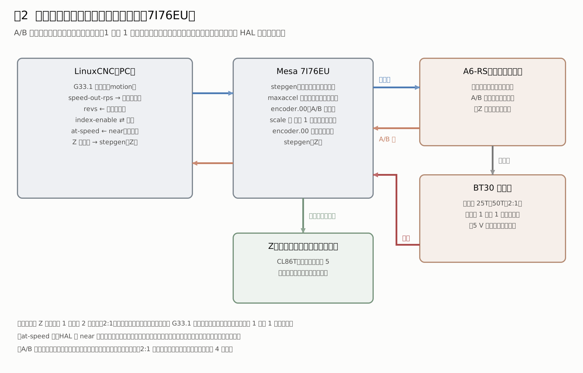
HAL example. The numbers assume stepgen 00 to 03 are used for two X motors, Y, and Z, and 04 is used for the spindle. Numerical values will be determined during commissioning.
# Spindle: velocity-mode stepgen
setp hm2_7i76e.0.stepgen.04.control-type 1
setp hm2_7i76e.0.stepgen.04.position-scale [SPINDLE_0]STEP_SCALE   # pulses per spindle rev
setp hm2_7i76e.0.stepgen.04.maxaccel 50                            # spindle rev/s². Reversal speed
net spindle-vel-cmd  spindle.0.speed-out-rps => hm2_7i76e.0.stepgen.04.velocity-cmd
net spindle-on       spindle.0.on            => hm2_7i76e.0.stepgen.04.enable

# Spindle position: A/B from servo, index from spindle sensor
setp hm2_7i76e.0.encoder.00.scale [SPINDLE_0]ENCODER_SCALE         # counts per spindle rev
net spindle-revs     hm2_7i76e.0.encoder.00.position    => spindle.0.revs
net spindle-vel-fb   hm2_7i76e.0.encoder.00.velocity    => spindle.0.speed-in
net spindle-index    hm2_7i76e.0.encoder.00.index-enable <=> spindle.0.index-enable

# At-speed: compare commanded and encoder speeds (without using a dedicated terminal)
loadrt near
addf near.0 servo-thread
net spindle-vel-cmd  => near.0.in1
net spindle-vel-fb   => near.0.in2
setp near.0.scale 1.05
setp near.0.difference 0.2
net spindle-at-speed near.0.out => spindle.0.at-speed
- Encoder scale: If the servo frequency-divided output is set to N lines per revolution, quadrature decoding yields 4N counts. One spindle revolution results in 8N counts (2:1). Rotate the spindle by hand to verify that
spindle.0.revsincreases by 1.0. If it does not increase in the M3 direction, invert the sign. - Index sensor: Attach a single marker, such as a screw head, to the spindle's 50T pulley. Detect this with a proximity sensor. Because the 7I76EU encoder input uses 5 V logic, a 24 V signal cannot be fed directly (common-mode range −7 to +12 V). If the sensor is NPN open-collector, power it at 12 to 24 V. Pull the output up to 5 V and feed it in (estimated; sensor and jumper settings will be verified during wiring).
- There are reports that the servo encoder output is noisy. [Forum] Keep it differential and wire it using twisted pairs. Leave the encoder filter enabled.
- No extra I/O terminals are used (the sensor uses the 7I76EU encoder index input).
3. Overshoot at the Bottom of the Hole
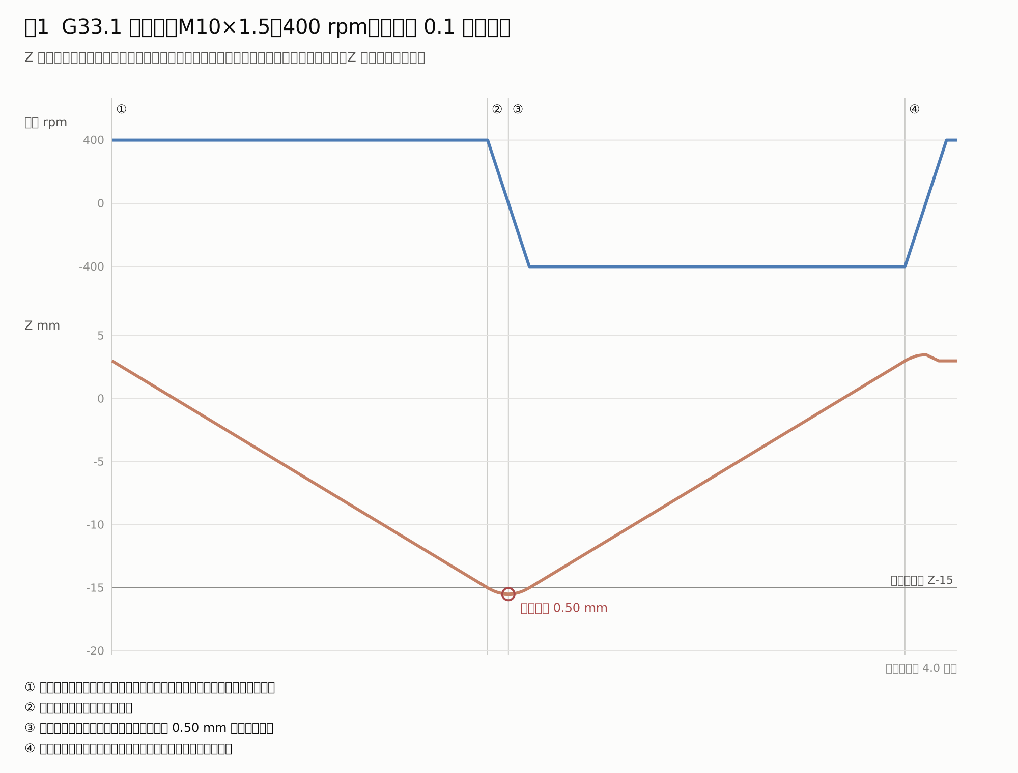
The Z axis continues down by the amount the spindle rotates between commanding reversal and coming to a complete stop. [Calculated from source behavior]
Overshoot = Pitch × Spindle speed / 60 × Deceleration time / 2
At the same cutting speed, a larger tap runs at a lower spindle speed but has a larger pitch, so overshoot is almost identical regardless of the tap diameter.
| Thread | Pilot hole | 5 m/min | 10 m/min | Z speed (10 m/min) | Overshoot (0.1 s to stop) | Same (0.2 s) | Z acceleration (0.1 s) |
|---|---|---|---|---|---|---|---|
| M3×0.5 | φ2.5 | 530 rpm | 1060 rpm | 530 mm/min | 0.44 | 0.88 | 88 mm/s² |
| M4×0.7 | φ3.3 | 400 | 800 | 560 | 0.46 | 0.93 | 93 |
| M5×0.8 | φ4.2 | 320 | 640 | 510 | 0.42 | 0.85 | 85 |
| M6×1 | φ5.0 | 265 | 530 | 530 | 0.44 | 0.88 | 88 |
| M8×1.25 | φ6.8 | 200 | 400 | 500 | 0.41 | 0.83 | 83 |
| M10×1.5 | φ8.5 | 160 | 320 | 480 | 0.40 | 0.80 | 80 |
| M12×1.75 | φ10.2 | 133 | 265 | 460 | 0.39 | 0.77 | 77 |
- Units are in mm. Time to stop is determined by stepgen's maxaccel. With a maxaccel of 50 rev/s², it stops in 0.11 s from 320 rpm. [Calculation]
- The motor torque needed for reversal is small. If we assume the inertia of the rotating parts is 1×10⁻³ kg·m² at the motor shaft (assumed; total of rotor, pulley, spindle, and holder, with actual values unverified), the torque is around 0.6 N·m. This is small compared to the maximum 11 N·m. [Calculation] The limits when reversing faster lie in the regenerative voltage and Z following.
- The acceleration needed for Z is under 100 mm/s². This is expected to be well below the feed acceleration setting. When returning with I2, the acceleration doubles at the reversal at the starting height.
- Pilot hole depth for blind holes = usable thread depth + chamfer (about 2.5 threads for a spiral tap) + overshoot (0.4–0.8) + 1 mm margin. We will replace the overshoot with the value measured with halscope during commissioning.
- For through holes, you do not need to worry about overshoot. Since much of this machine's work is drilling holes in plates, we will start using it with through holes.
4. Sources of Synchronization Error
| Source | Expected magnitude | Decision |
|---|---|---|
| How the spindle stops (overshoot) | 0.4–0.8 mm | Since Z moves following the spindle, this does not cause thread pitch errors. It only adds depth. |
| Belt stretch and key play | Key play of 0.05 mm (at the outer circumference of a φ19 shaft, assumed) is about 0.3°. About 0.001 mm in the M10 axial direction. | A/B monitors the motor. However, because of the 2:1 reduction, the axial error is small. [Calculation] In forums, there was also the opinion that "belt play breaks taps." However, we decided that does not apply with this machine's ratio. The key is secured with a setscrew (Spindle Pulley Strength Calculation). |
| Z lag (closed-loop stepping) | Unverified | Our biggest concern. During reversal, if Z lags behind the spindle, it pushes or pulls on the tap. We will check joint.N.f-error with halscope. We absorb this with the slight float in the holder. |
| Index position | Does not affect a single round trip | For pecking or re-entering the same hole, the spindle's 1 pulse per revolution becomes a source of misalignment. Mount the sensor so its position does not shift. |
Practical example: There is a report of running G33.1 with a 7I92H and an AC servo (step/direction) spindle. In this example, a Z following error occurred at I3, but did not occur at I1.5. [Forum] There is also a report of routinely tapping M3–M6 with a 7I76 and a ±10 V servo spindle (1:1.8, A/B on the servo, index on the spindle) (AC Servo as Spindle). For the control setup, see Control and Electrical Configuration.
5. Taps and Holders
Holders (Decision)
| Method | Axial compliance | Decision for this machine |
|---|---|---|
| Holding round shank with ER collet | None. Slips in rotation direction | We do not use this. If the tap slips when reversing, depth and phase get out of sync. |
| ER tap collet driven by square | None | Runner-up. Inexpensive (expected to be in the thousand-yen range each for overseas products, unverified). Can be used with our existing BT30-ER32 holders. Any sync error is transferred directly to the tap. |
| Synchro holder (with micro-float) | Approx. 0.2–0.5 mm | We chose this. Absorbs Z-axis lag and reduces axial load on the tap. Runout is small, too. BT30 models can be purchased from MISUMI for approx. ¥27,000–35,000 (tax excluded, search excerpt). Requires separate collets matching each tap size. |
| Tension-compression floating holder (GT12, etc.) | Several mm | Backup insurance. Lets you tap with G84 even while synchronization is not working properly. Thread accuracy drops, and runout also becomes larger. |
- Tool manufacturers recommend synchro holders with micro-compensation even for synchronized feed on machining centers (Gemini report; original source unread). Since Z lag is unverified on this machine, it is needed all the more.
- One holder uses one spot on the rack. We will include it in the number of tools for the Tool Changer Rack.
- We will select the holder model number based on the shank diameters of our existing taps and the rack length. Before ordering, verify the model number and included collets.
Taps and Conditions
- Through holes: spiral point taps (push chips forward). Blind holes: spiral flute taps. We use what we have on hand.
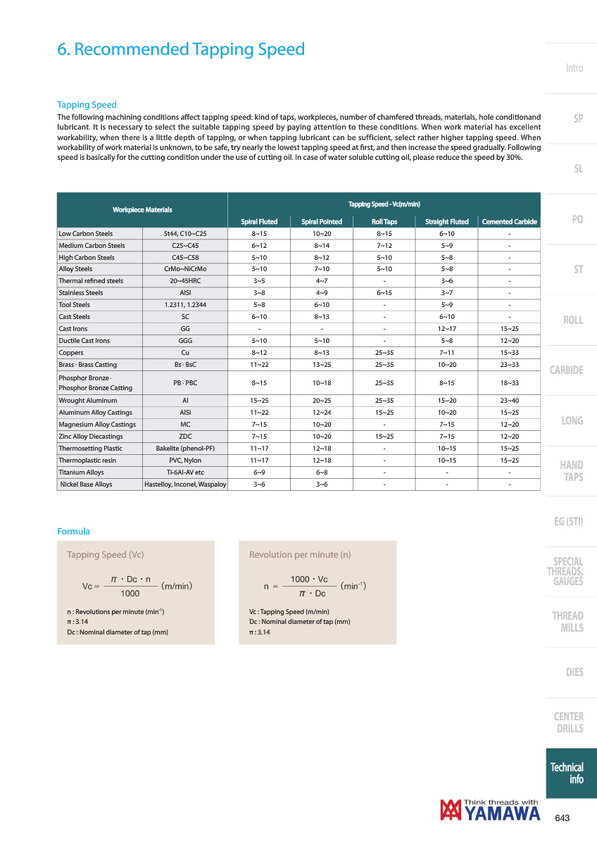
- Cutting speed: OSG recommends 5–15 m/min for medium/high carbon steel (S45C) with A-SFT, and recommends synchronized feed machines for 15 m/min or higher (assuming water-soluble coolant). [Original source] Yamawa's table specifies 8–13 for spiral and 10–20 for spiral point in low-carbon steel (SS41, etc.), and 6–12 for spiral and 8–14 m/min for spiral point in medium-carbon steel (C25–C45). This assumes neat oil, and notes that speeds should be reduced by 30% if using water-soluble coolant. [Original source] We will start this machine at 5 m/min and increase to 10 m/min if there are no problems.
- Coolant: This machine does not have a flood coolant system, so we apply tapping oil with a brush or dropper.
- Pecking: Tap manufacturers recommend cutting in a single pass in principle (Gemini report). Only for blind holes where the depth exceeds twice the diameter do we use the pecking below. There are reports that pecking in stainless steel caused the thread to become oversize. [Forum]
Torque
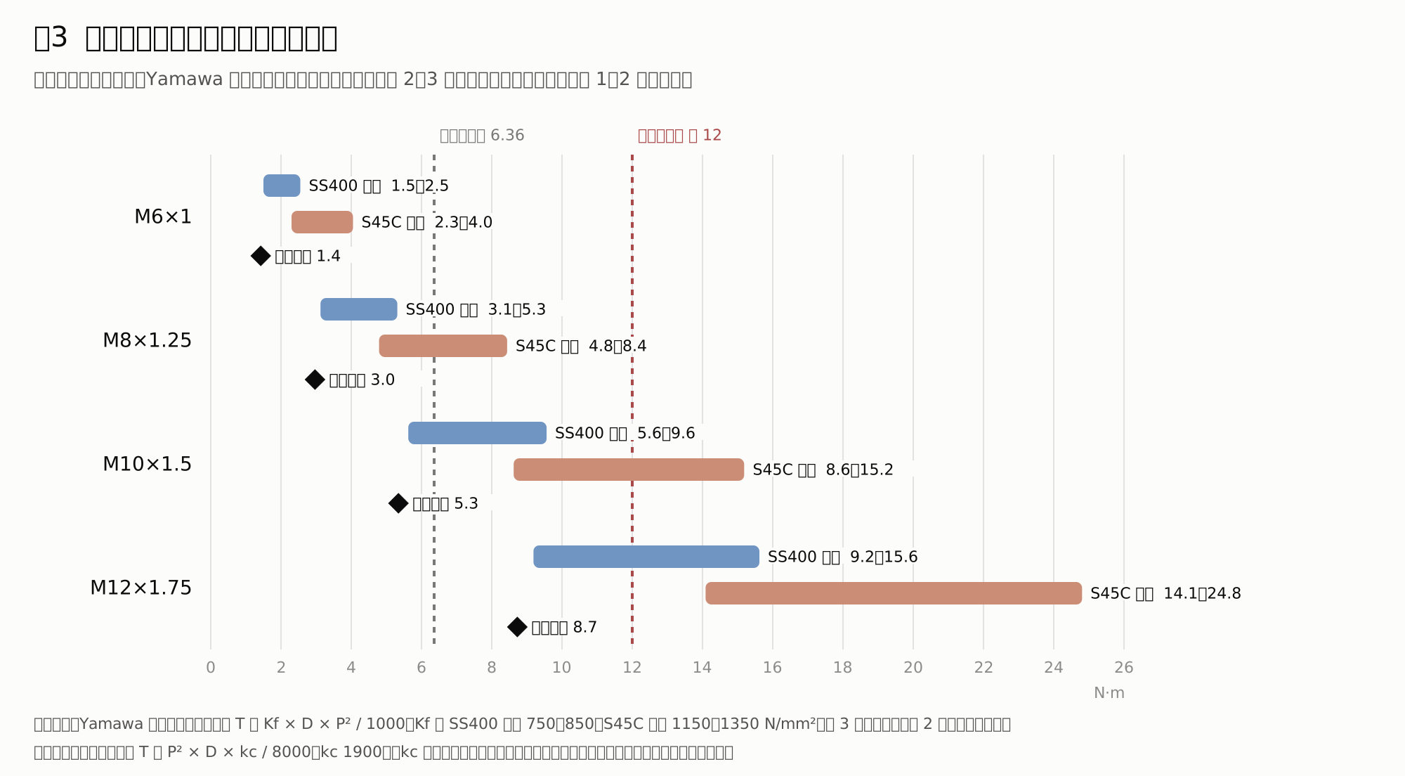
| Thread | Rule-of-thumb formula | Calculated back from Yamawa, SS400, etc. | Same, S45C, etc. | Spindle (rated 6.36, torque limit approx. 12) |
|---|---|---|---|---|
| M6 | 1.4 | 1.5 to 2.5 | 2.3 to 4.0 | Within rated range |
| M8 | 3.0 | 3.1 to 5.3 | 4.8 to 8.4 | SS400 is within rated range. S45C exceeds rated, but within limit |
| M10 | 5.3 | 5.6 to 9.6 | 8.6 to 15.2 | SS400 is within limit (margin is small). S45C may exceed limit |
| M12 | 8.7 | 9.2 to 15.6 | 14.1 to 24.8 | Exceeds limit. We use a thread mill |
Units are N·m. The torque limit is the value determined from the belt force (Control and Electrical Configuration). If it hits the limit, the servo lags and Z follows the spindle, so the thread is expected to stop without stripping (estimated).
Why the torque estimates differ
| Estimate | Value for M10 | Details | Reliability |
|---|---|---|---|
| Rule-of-thumb formula (Cutting Force Calculations) | 5.3 | T = P² × D × kc / 8000, kc 1900 (drilling guideline for SS400) | Source of the formula is unverified |
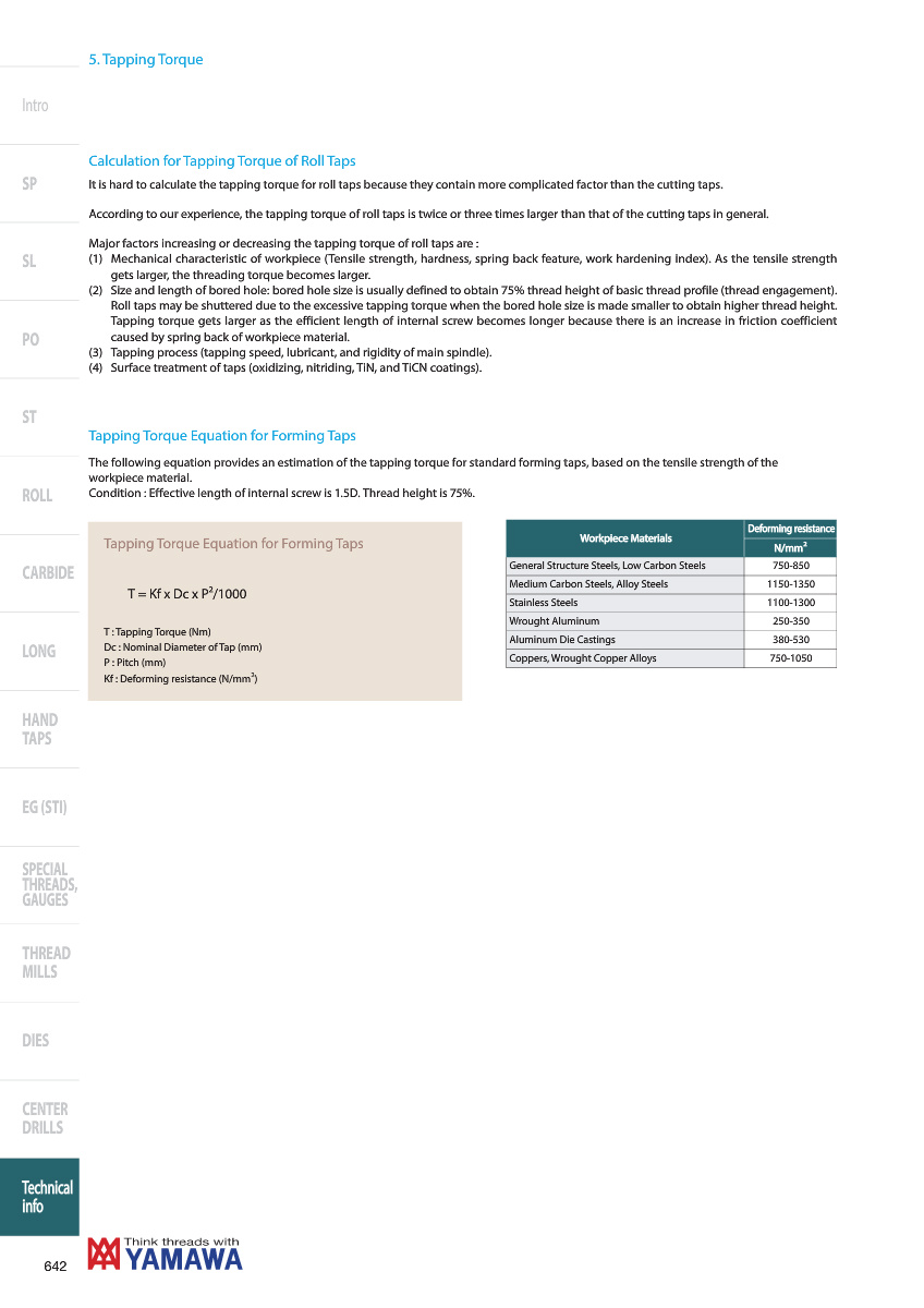
| Calculated back from Yamawa's roll tap formula | SS400 etc. 5.6 to 9.6, S45C etc. 8.6 to 15.2 | Roll tap T = Kf × D × P² / 1000 (female thread length 1.5D, 75% thread engagement). Stated that "roll tap torque is 2 to 3 times that of cutting taps", so divided by 2 and 3 | [Original source] However, the back-calculation is my own conversion |
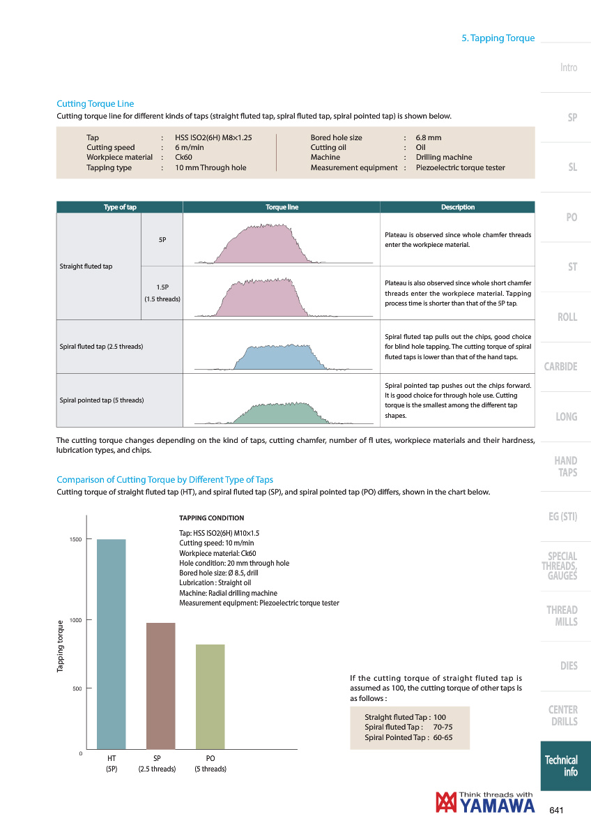
| Yamawa's measured bar graph | HT 1500, SP approx. 900, PO approx. 750 | M10, Ck60 (equivalent to S60C), 10 m/min, non-water-soluble oil, 20 mm through hole, φ8.5 pilot hole, piezoelectric dynamometer | [Original source] No units written on the axis. Reading it as N·cm gives SP approx. 9, PO approx. 7.5 N·m (estimated) |
| Gemini's 1st attempt | 10 to 15 | Claimed as "OSG's S45C torque chart" | Cannot find the original source |
| Gemini's 2nd attempt | 7.52 | Claimed as "OSG A-SFT, S45C, 20 m/min" | The provided source image was unrelated, and Yamawa's page number was also incorrect. Do not use |
- The rule-of-thumb formula takes the same form as the torque derived from the work of "volume cut away × specific cutting force". The volume cut per revolution is the cross-section of the internal thread groove (roughly half between the pilot hole and the thread outer diameter) × pitch. For M10, this is about 10.9 mm² × 1.5 mm = 16 mm³. Multiplying this by 1900 and dividing by 2π gives 4.9 N·m. Almost the same as the formula's 5.3. [Calculation]
- Actual tapping torque is larger than this. There are 3 reasons.
- The chips are thin. Cutting is divided across the 2.5 to 5 chamfer teeth and the number of flutes, so depth of cut per tooth is around 0.1 mm. Since specific cutting force increases as chips get thinner, it is higher than the 1900 for drilling (estimated).
- The thread teeth behind the chamfer rub against the internal thread surface. This is not included in the formula.
- In blind holes, chips pack in, and torque also increases due to wear.
- In Yamawa's comparison of tap types, taking hand taps as 100, spiral fluted taps are 70 to 75, and spiral point taps are 60 to 65. [Original source] Spiral point taps are the lowest.
- Decision: For SS400, we expect 1 to 2 times the rule-of-thumb formula, and for S45C, 1.6 to 3 times. For SS400, we keep our previous decision: "M10 can be used for short durations, M12 and larger will use a thread mill." For M10 in S45C, torque may exceed the limit, so thread milling is the primary choice. During commissioning, we will measure it using the A6-RS torque display and replace this table.
6. Writing the G-code
G21 G90 G17 G40 G80
G0 X50 Y30                  (To hole position. Do not write XY in G33.1)
G0 Z3                       (Start height. Allow margin for spindle acceleration and synchronization)
S160 M3                     (M10, 5 m/min)
G33.1 Z-15 K1.5             (M10×1.5. For blind holes, goes 0.4 to 0.8 deeper)
G0 Z10
M5
Pecking (repeating G33.1 with increasing depth in the same hole). G33.1 returns to the start height each time, and the position aligns via the index.
o<peck_tap> sub
  (#1 final depth  #2 pitch  #3 depth per peck  #4 start height)
  #<z> = #4
  G0 Z#4
  o100 while [#<z> GT #1]
    #<z> = [#<z> - #3]
    o101 if [#<z> LT #1]
      #<z> = #1
    o101 endif
    G33.1 Z#<z> K#2
  o100 endwhile
o<peck_tap> endsub
- Fusion's post-processor for LinuxCNC outputs tapping as G33.1 (there are forum reports of people without encoders having trouble with this). [Forum] On this machine, it works as is.
- During G33.1, feed override and feed hold do not work. If you want to stop, it must be an emergency stop, leaving the tap in the hole.
- We do not use I (retract speed multiplier) at first. We will try it starting from 1.5 after commissioning.
7. Thread Milling (A Method That Doesn't Need Synchronization)
Added 2026-11-05. Since our policy is to use thread milling for M12 and above and for M10 in S45C, we checked whether this machine can cut properly.
Why synchronization isn't needed
- The spindle simply rotates at a set speed with M3. Spindle position is not used, so neither an encoder, an index sensor, nor at-speed are required. It can be used even before completing rigid tapping commissioning (Sections 2 and 8).
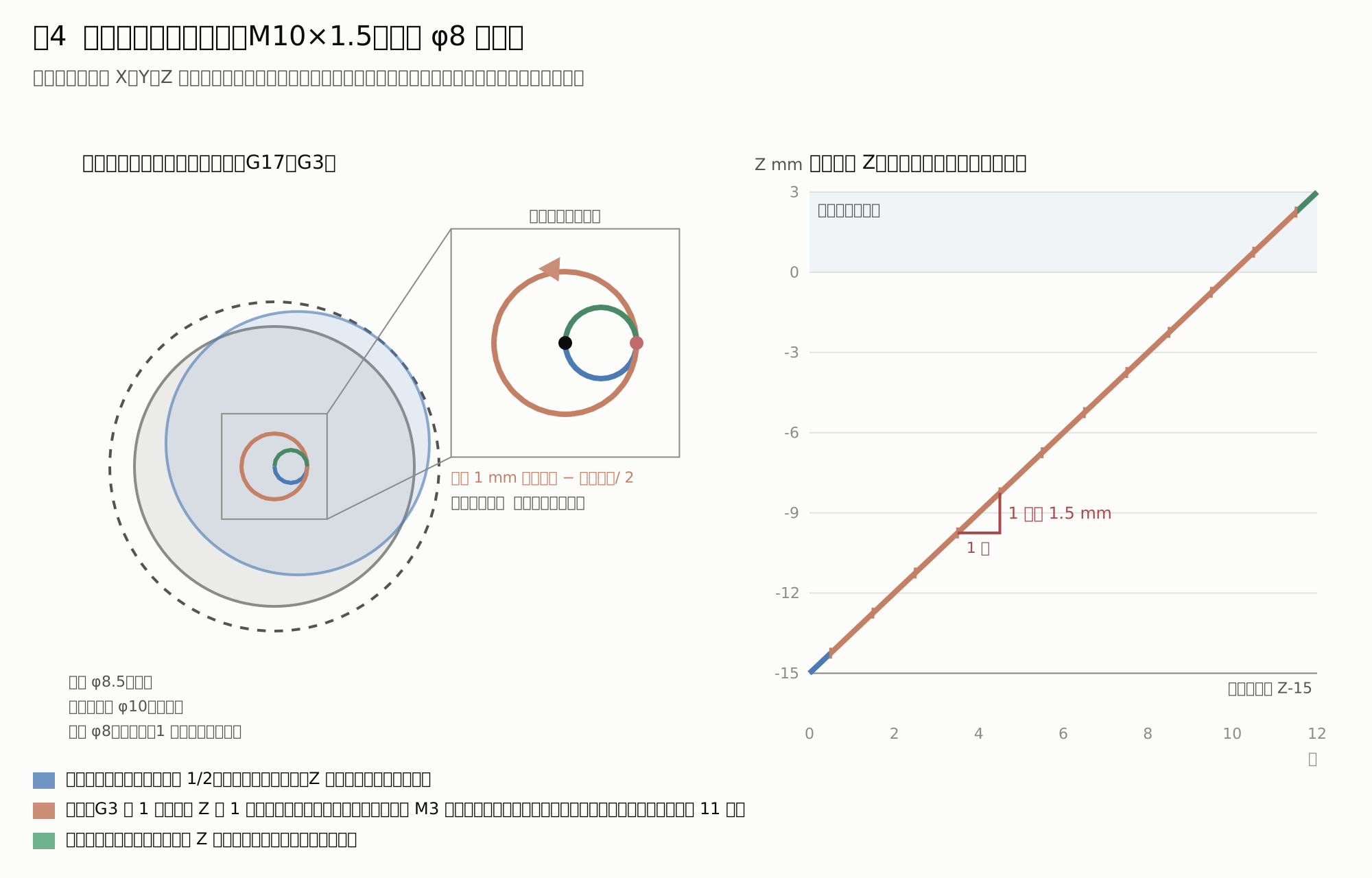
- The thread pitch is determined solely by X, Y, and Z interpolation. Specifying Z in G2/G3 creates a helical movement. Z rises by 1 pitch per revolution (Figure 4). The three axes move together under LinuxCNC's unified trajectory calculation. Therefore, Z advance is proportional to the circle angle. [Original source] (Specifying Z in G2/G3)
- Even if Z always lags by the same amount, the pitch does not change. Only the thread phase shifts slightly. The "Z lag during reversal" we worried about with rigid tapping does not occur with thread milling (it does not reverse inside the hole).
- Tool forces are small. Single-point tools only cut a portion of one thread crest at a time. There is no worry of hitting the torque limit (approx. 12 N·m). [Calculation expectation]
What takes effect instead
| Source | Effect on the thread | Expectation on this machine |
|---|---|---|
| XY circular errors (play, reversal lag) | Twice the radius error becomes the pitch diameter error | If the play in the guides and screws is 0.010 mm (Machining Methods for Accurate Holes), the pitch diameter error is around 0.02 mm. This is small compared to the 0.18 mm tolerance for an M10×1.5 6H pitch diameter (9.026 to 9.206 mm, ISO values; source unread). [Calculation] |
| Tool deflection | The thread becomes undersized. It gets narrower toward the bottom (tool tip) | Cut in two passes, then trace once more at the same diameter (spring pass). |
| Tool runout | The thread becomes oversized | Minimize holder runout. Start with the ER collets on hand and measure the runout. |
| Z lead screw pitch error | Pitch error | Expected to be under 0.01 mm for a thread length of 15 to 20 mm (estimated; grade of the Z ballscrew is unverified). |
| Small circular motion | If the circularity is poor, the pitch diameter will vary | When cutting an M10 thread with a φ8 tool, the tool center only moves along a circle with a radius of 1 mm (Fig. 4). The machine play shows up directly. Check this with a test hole. |
- You can adjust the thread size later. This is an advantage taps do not have. If the gauge is tight, increase the "diameter offset" in the program by 0.01 to 0.02 mm at a time (see the G-code below). You can also adjust it using cutter radius compensation (G41/G42).
- Even if a tool breaks, it rarely gets stuck in the hole. Cleaning up afterward is much easier compared to a tap breaking off inside a hole (estimated).
Spindle Speed and Feed Rate
The table for the OSG AT-2 (thread mill) lists 115 to 180 SFM (approx. 35 to 55 m/min) for low-carbon steel (up to C 0.25%), 260 to 525 SFM (approx. 79 to 160 m/min) for medium-carbon steel (C 0.25 to 0.45%), and a feed per tooth of 0.0004 to 0.0028 in (approx. 0.01 to 0.07 mm). It assumes an air blow and notes that cutting conditions should be adjusted based on machine and clamping rigidity. [Source] The AT-2 is a left-hand cutting tool (rotated with M4). Therefore, use these figures as a guideline and redetermine them based on the catalog data for the specific tool you purchase.
| Thread | Tool diameter (example) | Spindle speed at 35 m/min | Spindle speed at 79 m/min | Cutting speed at 3000 rpm | Decision |
|---|---|---|---|---|---|
| M6×1 | φ4.7 | 2370 rpm | 5350 rpm | 44 m/min | Achievable for SS400. Not achievable for S45C |
| M8×1.25 | φ6 | 1860 | 4190 | 57 | Same as above |
| M10×1.5 | φ8 | 1390 | 3140 | 75 | Achievable for SS400. Slightly falls short for S45C |
| M12×1.75 | φ9.5 | 1170 | 2650 | 90 | Achievable for both |
| M16×2 | φ12 | 930 | 2100 | 113 | Achievable for both |
- The maximum spindle speed is 3000 rpm. The tool diameters are examples and will depend on the tools you buy. The tool must be smaller than the pilot hole diameter (at least 8.376 mm for M10) to enter the hole. [Calculation]
- For small threads in S45C, the machine cannot reach the recommended cutting speed. Machining must be done slower at 3000 rpm. Running carbide tools slowly can reduce tool life and surface finish (estimated). For S45C threads of M8 and below, we use taps first (M8 is within the torque limit, Section 5).
- Write the feed rate based on the tool center speed. Center feed rate = tip feed rate × (thread major diameter − tool diameter) / thread major diameter. When cutting M10 with a φ8 tool, this drops to 1/5 of the tip feed rate. [Calculation]
- Example: M10 in SS400, φ8 3-flute tool, 1600 rpm (40 m/min), feed per tooth 0.03 mm (toward the lower end considering rigidity). The tip feed rate is 144 mm/min, and the center feed rate is approx. 29 mm/min. For a depth of 15 mm (11 revolutions), one pass takes approx. 2.5 min; two passes plus finishing take approx. 7 min. [Calculation] This is slower than tapping. Because of this, taps are better suited for SS400 threads of M10 and below when there are many holes.
G-code
Subroutine for a single-point thread mill (a tool that cuts one pitch per revolution). It spirals upward using G3 (climb milling when cutting a right-hand thread with an M3 right-hand cutting tool). This matches the motion shown in Fig. 4.
o<thread_mill> sub
  (#1 X  #2 Y  #3 Thread major diameter  #4 Pitch  #5 Tool diameter)
  (#6 Thread bottom Z  #7 Thread top Z  #8 Diameter offset  #9 Feed: tool center)
  #<r> = [[#3 + #8 - #5] / 2]           (Radius of the tool center circle)
  #<n> = [FIX[[#7 - #6] / #4] + 1]      (Number of revolutions. Always exceeds the top end)
  G0 X#1 Y#2
  G0 Z[#7 + 2]
  G1 Z#6 F[#9 * 5]                       (Descend at the center of the pilot hole)
  #<z> = [#6 + #4 / 2]
  G3 X[#1 + #<r>] Y#2 Z#<z> I[#<r> / 2] J0 F#9      (Lead-in: semi-circle)
  #<k> = 0
  o110 while [#<k> LT #<n>]
    #<z> = [#<z> + #4]
    G3 X[#1 + #<r>] Y#2 Z#<z> I[0 - #<r>] J0          (One pitch per revolution)
    #<k> = [#<k> + 1]
  o110 endwhile
  G3 X#1 Y#2 Z[#<z> + #4 / 2] I[0 - #<r> / 2] J0    (Lead-out: semi-circle to center)
  G0 Z[#7 + 2]
o<thread_mill> endsub
G21 G90 G17 G40 G80 G64 P0.005
S1600 M3                                 (SS400, φ8, 40 m/min)
o<thread_mill> call [50] [30] [10] [1.5] [8] [-15] [0] [-0.3] [29]   (1st pass: diameter 0.3 smaller)
o<thread_mill> call [50] [30] [10] [1.5] [8] [-15] [0] [0] [29]      (2nd pass: finish)
o<thread_mill> call [50] [30] [10] [1.5] [8] [-15] [0] [0] [29]      (One more pass at the same diameter: spring pass for deflection)
G0 Z10
M5
- I and J are relative to the circle center (G91.1, default). XY is absolute (G90).
- G64 P0.005 prevents over-smoothing at the transition between revolutions. G61 is also fine.
- For blind holes, make the pilot hole deeper than the bottom of the thread to account for the shape of the tool tip (about one pitch).
- Some tools use left-hand cutting (run with M4). In that case, adjust the rotation direction and the G2/G3 direction according to the tool instructions.
- Check the result with a thread gauge (go / no-go). If it is tight, increase the "diameter offset". Keep a record of the dialed-in value for each tool.
Conclusion
- Thread milling is expected to cut cleanly on this machine. There are no synchronization issues. The factors that matter are the XY circular accuracy and tool deflection. Both are either smaller than thread tolerances or can be dialed in after the fact.
- Our policy remains unchanged: use thread milling for everything M12 and larger, and make thread milling the first choice for S45C M10. When tapping many holes of M10 or smaller in SS400, use taps because they take less time.
- Commissioning: measure the circular accuracy first with the SS400 φ25 helical interpolation test from Machining Methods for Accurate Holes. After that, cut an M12 thread in SS400 scrap stock and verify it with a thread gauge. This can be done before rigid tapping.
8. Commissioning Procedure
- Spindle direction and scale. Turn the spindle 1 revolution by hand. Make sure
spindle.0.revsincreases by 1.0. It must increase positively with M3. - Index. Run the spindle. Raise
index-enableand make sure it drops within 1 revolution. - Reversal. Switch between M3 and M4. Make sure the A6-RS doesn't trip with an overvoltage fault. If it trips, lower maxaccel or reconsider the regenerative resistor. There are reports of stepper spindles tripping with overvoltage after stopping abruptly. [Forum]
- G33.1 in air. Use halscope to capture
spindle.0.revs, commanded and actual Z positions, andjoint.N.f-error. Measure the overshoot and Z lag during reversal. Replace the overshoot values in the table with your measured values. - Through-holes in SS400 scrap for M6, M8, and M10. Check them with a thread gauge.
- Blind holes. Only after deepening the pilot holes based on the measured overshoot.
- M3 to M5. Do these last since they break easily.
- If execution stops in the middle of G33.1, respecify all modes like G80 at the start of the next program. There are reports of rapid, non-synchronized movements occurring after an interruption. [Forum]
- Decide how to retract the tap if it gets stuck in a hole before starting your tests. Either turn the spindle in reverse by hand while inching Z upward, or remove the whole holder.
9. Uncertain Points
- Output divider settings and differential output levels for the A6-RS. Need to check the manual.
- Lag during reversal on Z (closed-loop stepper). Won't know until measured on the actual machine.
- Inertia of the rotating parts and regenerative voltage during reversal.
- Part numbers, collets, and prices for synchronized tapping holders. The MISUMI price is from a search snippet; I haven't read the page.
- Measured tap torque values. There is a 1x to 3x difference between the rule-of-thumb formula and back-calculations from Yamawa's documentation (Section 5). Yamawa's measured bar chart doesn't list units.
- I haven't yet found reports of successful rigid tapping with the 7I76EU and A6-RS combination (though successful examples exist with similar setups).
- Thread mills: part number of the tool to buy, number of flutes, recommended conditions. Accuracy of small circles around 1 mm radius in XY. Ball screw grade on Z. The 6H tolerance values haven't been checked against the original ISO standard (Section 7).
10. Sources
- LinuxCNC G-Codes (G33.1, G84). 2.10 documentation.
- motion(9) (spindle.M.* pins)
- INI Configuration ([SPINDLE_n])
- Rigid peck tapping (pecking by repeating G33.1, lead-in distance, and at-speed checking)
- emc-users: G33.1 error (7I92H with AC servo spindle, tracking error with I3, method of measuring overshoot and subtracting it from depth)
- G33.1 rigid taping on a mill leads to a couple unexpected events (behavior when XY is specified, behavior after stopping)
- Non rigid tapping (Fusion post-processor outputting G33.1; search snippet)
- OSG A-SFT Flyer (cutting speeds; search snippet)
- Technical documentation from Yamawa European Catalogue 2021: Tapping torque (measurements, comparing tap types), Roll tap torque formula, Cutting speed table
- OSG A Brand AT-2 Speeds & Feeds (thread mill cutting speeds and feeds, left-hand cut, assuming air blow)
- Four queries to Gemini (with search): how to use G33.1, servo spindle experiences, holders, and SS400 conditions. Used as clues; only items verified against primary sources were included in the text.
QR code for this page
https://robo100.jp/en/000023
No comments yet.