Calculating Cutting Forces
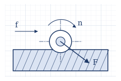
Here, we calculate the forces exerted on the spindle and machine during drilling, tapping, and milling. These are all trial calculations and are unverified on the actual machine.
Conditions
- Specific cutting force kc: 1900 N/mm² for drilling, 2000 N/mm² for milling (rough guide for SS400. (unverified))
- Machining conditions: records from machining actual products
Drilling
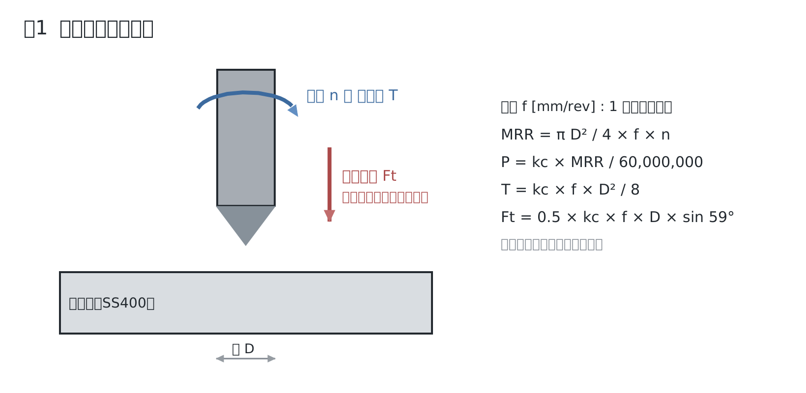
Example: carbide φ12, 1250 rpm, feed 0.07 mm/rev
- Material removal rate: MRR = π × 12² / 4 × 0.07 × 1250 = 9,896 mm³/min
- Net power: P = 1900 × 9,896 / 60,000,000 = 0.313 kW
- Spindle torque: T = 1900 × 0.07 × 12² / 8 = 2,394 N·mm = 2.39 N·m
- Thrust (cutting edges only): Ft = 0.5 × 1900 × 0.07 × 12 × sin 59° = 684 N
Because the contribution from the chisel edge varies depending on the tool, we estimate the thrust at 1000–1500 N, and use 1500 N for structural calculations.
| Operation | Spindle speed | Feed | MRR mm³/min | Power kW | Torque N·m | Cutting edge thrust N |
|---|---|---|---|---|---|---|
| Carbide φ12 | 1250 | 0.07 | 9,896 | 0.313 | 2.39 | 684 |
| φ25 | 210 | 0.07 | 7,216 | 0.229 | 10.4 | 1,425 |
| φ35 | 210 | 0.07 (assumed) | 14,143 | 0.448 | 20.4 | 1,995 |
| HSS φ12 | 660 | 0.20 | 14,929 | 0.473 | 6.84 | 1,954 |
Note: For φ25 and φ35, the cutting edges alone generate 1400–2000 N, and adding the chisel edge will exceed the 1500 N used in the structural calculation. This matches our policy of limiting drilling on this machine to φ12, and machining larger diameters with helical interpolation.
Tapping
T = P² × D × kc / 8000 (P is the pitch; formula source is unverified. Increases with wear)
| Size | Formula | Torque N·m |
|---|---|---|
| M8×1.25 | 1.25² × 8 × 1900 / 8000 | 2.97 |
| M10×1.5 | 1.5² × 10 × 1900 / 8000 | 5.34 |
| M12×1.75 | 1.75² × 12 × 1900 / 8000 | 8.73 |
| M14×2 | 2² × 14 × 1900 / 8000 | 13.3 |
Note (2026-11-05): This formula has the same form as torque derived from removed volume and specific cutting force work, and yields the lowest estimate. Calculating back from Yamawa's roll tap formula gives 1 to 2 times this value for SS400, and 1.6 to 3 times for S45C (5.6–9.6 and 8.6–15.2 N·m for M10). For comparisons and reasoning, see Section 5 of How to Use Rigid Tapping.
Milling
P = kc × width × depth of cut × feed / 60,000,000, T = P / ω, Tangential force = T / radius
| Operation | MRR | Power | Torque | Tangential force |
|---|---|---|---|---|
| φ25 slotting, Z5, 1250 rpm, feed 60 | 25×5×60 = 7,500 | 0.25 kW | 250 / 130.9 = 1.91 N·m | 1.91 / 0.0125 = 153 N |
| φ63 face milling, 800 rpm, feed 240, depth of cut 0.5 (assumed) | 63×0.5×240 = 7,560 | 0.25 kW | 252 / 83.8 = 3.01 N·m | 3.01 / 0.0315 = 95 N |
Comparison with Spindle Capability
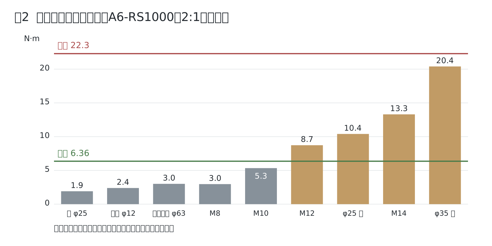
For the rated 6.36 N·m and maximum 22.3 N·m, see Spindle Drive Calculations. Since M12 and larger or φ25 and larger exceed the rated torque, keep them to short periods.
QR code for this page
https://robo100.jp/en/000009
No comments yet.