Calculations for Spindle Drive and Tool Release
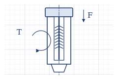
Calculations for the A6-RS1000H2A1-M17, a 2:1 reduction, and a φ100 cylinder. These are trial calculations and are unverified on the actual machine.
Reduction
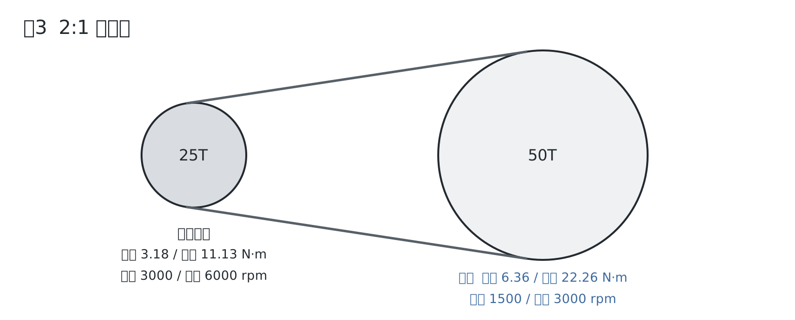
- Reduction ratio: 50 / 25 = 2
- Spindle torque: rated 3.18 × 2 = 6.36 N·m, maximum 11.13 × 2 = 22.26 N·m (excluding belt losses)
- Spindle speed: rated 3000 / 2 = 1500 rpm, maximum 6000 / 2 = 3000 rpm
The maximum speed at 200V is unverified. For spindle orientation, the same motor angle corresponds to two spindle angles (180° apart), so it will work fine as long as the drive keys are symmetrical.
For the pulley strength, see Spindle Pulley Strength Calculation.
Tool Release
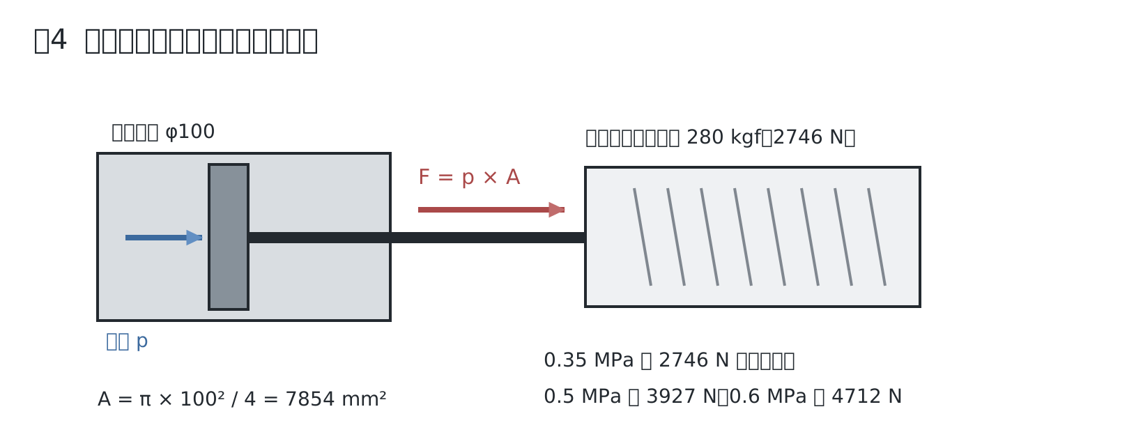
- Cylinder area: A = π × 100² / 4 = 7,854 mm²
- Drawbar retention force: 280 kgf × 9.81 = 2,746 N (as listed on the sales page)
- Balancing pressure: 2,746 / 7,854 = 0.35 MPa
- 3,927 N (400 kgf) at 0.5 MPa, 4,712 N (480 kgf) at 0.6 MPa
Because a spring's force increases the more it is compressed, it might require more than 2,746 N at the end of the release stroke. We will verify this on the actual machine, including friction. The 4.5 mm stroke is the rating on the spindle head, so a 10 mm cylinder stroke will be plenty.
Thrust and Taper
Drilling thrust pushes the holder further into the taper, so it does not compete with the drawbar retention force. What actually matters is the axial load capacity of the bearings, which remains unverified.
QR code for this page
https://robo100.jp/en/000010
No comments yet.