Feed Axis Calculations
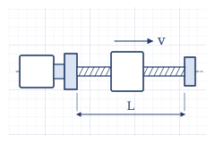
Calculating the ballscrew torque, spindle speed, length, critical speed, buckling, and rigidity. Lead: 5 mm, efficiency: 0.9 (assumed).
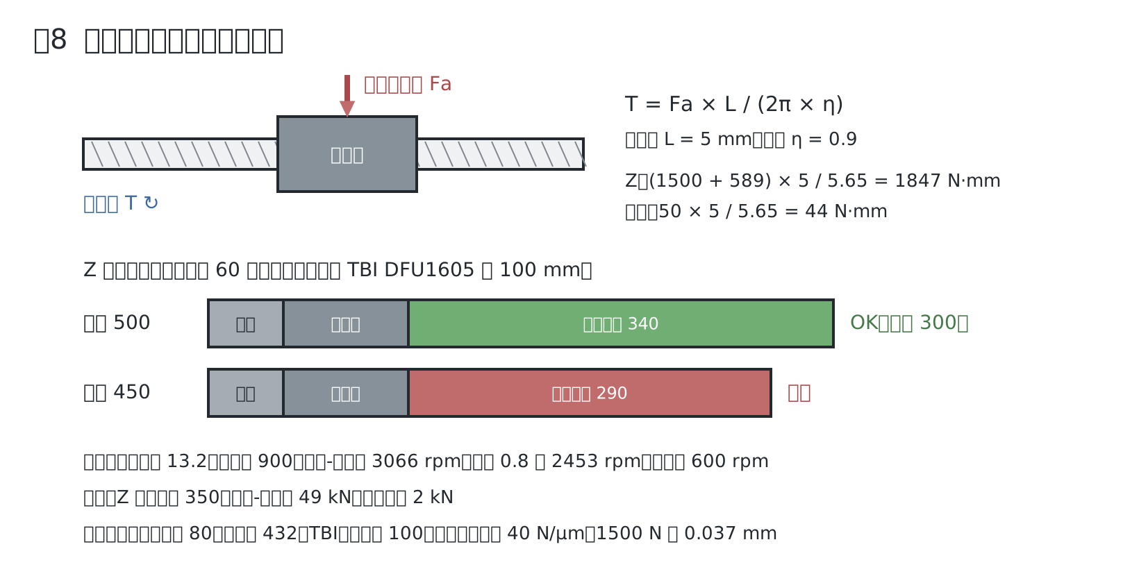
Torque
- Z: Thrust 1500 N + dead weight 60 kg × 9.81 = 589 N, totaling 2,089 N. T = 2,089 × 5 / (2π × 0.9) = 1.85 N·m (excluding acceleration and friction)
- Horizontal: 100 kg × 0.5 m/s² = 50 N. T = 50 × 5 / (2π × 0.9) = 0.044 N·m (excluding guideway friction)
The 8 N·m for Z and 3 N·m for horizontal are holding torques, which drop with spindle speed. Check the values at 600 rpm on the torque-speed curve (unverified).
Spindle Speed
- Rapid traverse 3 m/min: 3000 / 5 = 600 rpm
- Feed for φ12: 0.07 × 1250 = 87.5 mm/min, 87.5 / 5 = 17.5 rpm. Watch out for low-speed pulsation
Z-axis Length
With a stroke of 150, the effective length of the screw is stroke 150 + nut 100 + margin, so the distance between the supports is about 320, and the overall length is about 380.
Critical Speed (Rail Direction)
- Root diameter 13.2 mm (temporarily using the value for THK BIF1605): I = π × 13.2⁴ / 64 = 1,490 mm⁴, A = 137 mm²
- Span between supports 900 mm, fixed-supported, λ = 3.927
- ω = λ² / l² × √(E I / (ρ A)) = 15.42 / 0.81 × 16.86 = 321 rad/s = 3,066 rpm
- With a safety factor of 0.8, it is 2,453 rpm. Since we operate at 600 rpm, there is no problem
Buckling
- For Z, a span between supports of 320 or less is on the safe side using the value for 350. Z, span between supports 350, fixed-supported: P = 2 π² E I / L² = 49 kN. Operating load is about 2 kN
- Sufficiently large compared to the total of downward thrust and dead weight
Axial Rigidity (Z)
- Screw: E A / L = 205,000 × 137 / 350 = 80 N/µm
- Nut: 44 kgf/µm × 9.81 = 432 N/µm (TBI table)
- Bearing: 100 N/µm (assumed)
- Total: 1 / (1/80 + 1/432 + 1/100) = 40 N/µm. At 1500 N, this is 0.037 mm
Since this is in the feed direction, it does not affect hole position, but affects blind hole depth.
QR code for this page
https://robo100.jp/en/000011
No comments yet.